Sony KV-13M42 - S-Video Mod
This guide will cover how to S-Video mod the 13” Sony KV-13M42 BA-4D Chassis.
With the way I did this install, S-Video will be on Video 1 and composite on Video 2, but they will both use the same audio inputs. It is possible (and relatively easy) to have them use their own audio inputs, and I will note how to do that in the section of the guide that covers the audio portion.
Step 1: Enable Video 2 and S-Video in the Service Menu
This set by default does not have Video 2 enabled, nor can it use its S-Video inputs on the jungle chip’s Video 1 inputs. This is because of a setting in the service menu.
To get into the service menu, with the TV off, press Display -> 5 -> Volume Up -> Power on the remote. To change what setting you are editing you press 1 or 4 on the remote, and to change the value of the setting you press 3 or 6.
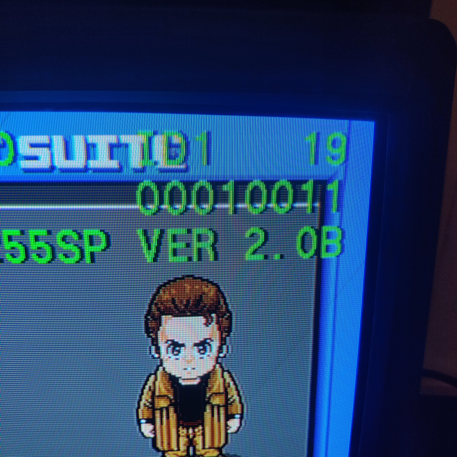
Once you are in the service menu, go to the setting labelled ID 1 and change its value to 19 or 00010011. It is normally set to 1 or 00000001. What this does is tell the microcontrollers in the set that this TV has S-Video input and also has a second video input. Specifically (with the first bit on the right being bit 0), bit 1 being set to 1 turns on the second video input (Video 2), and bit 4 set to 1 turns on S-Video on Video 1. Your ID1 setting should look like the photo below.
Step 2: Remove and Install Components
Open up your CRT and pull out the PCB. You may need to unplug some connectors to do so. Be sure to discharge the CRT before working on it!
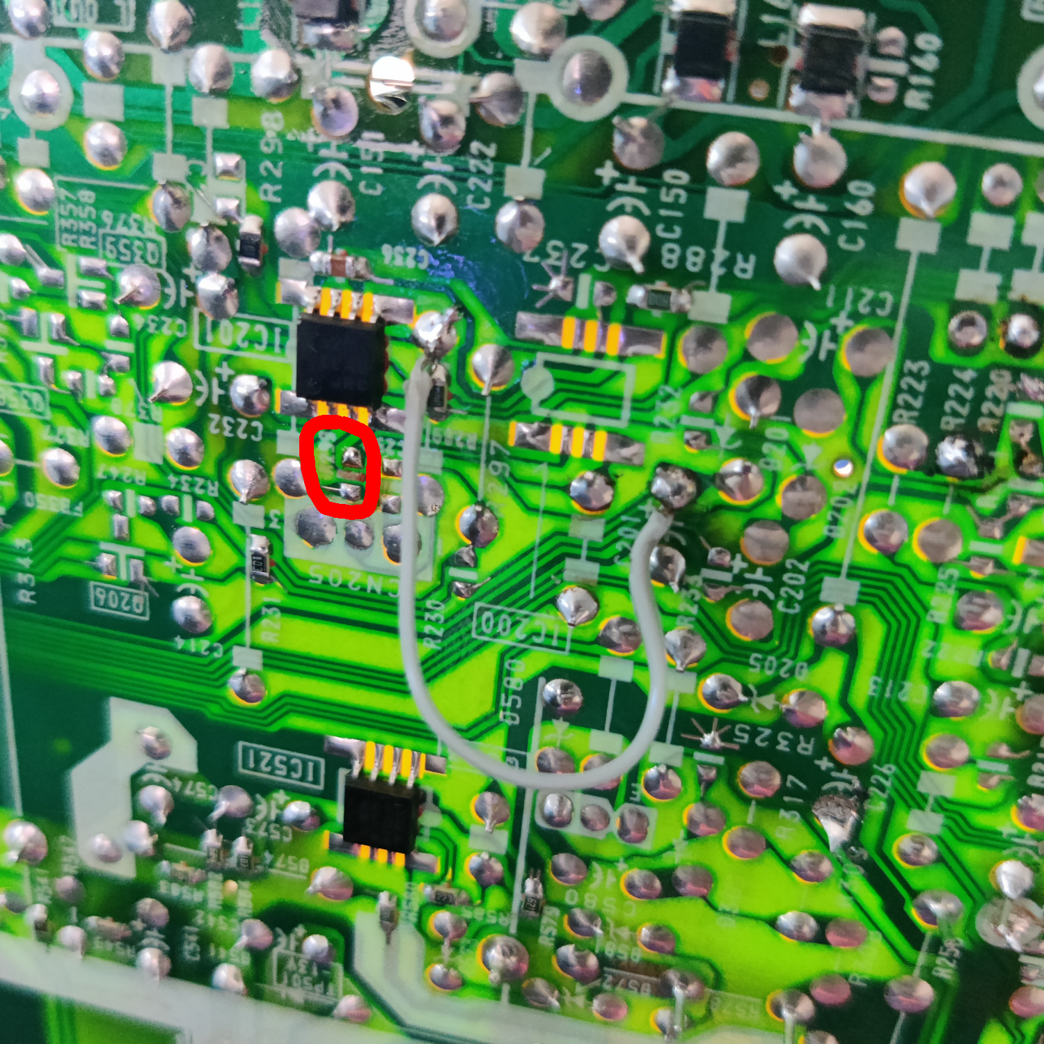
On the bottom of the PCB, locate R299 near IC201 and remove it.
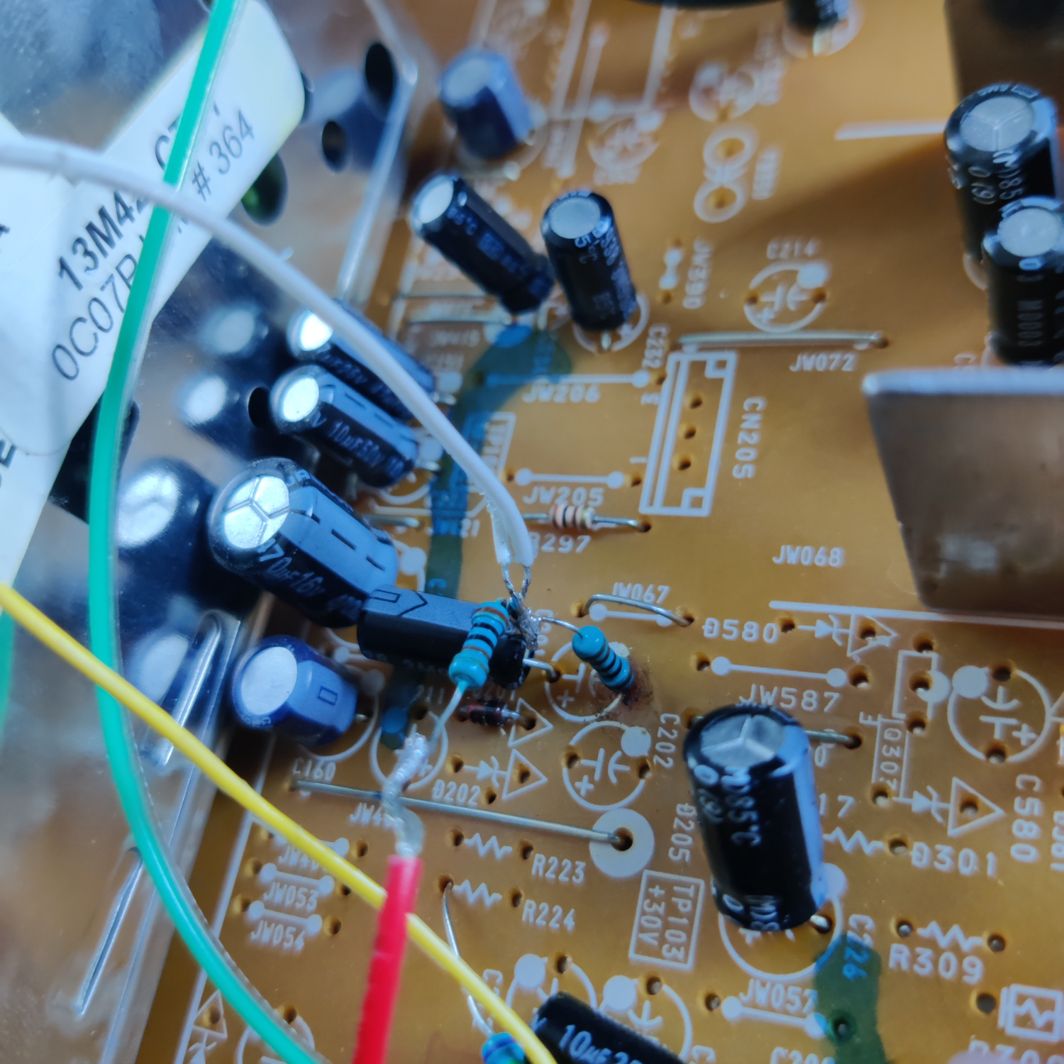
Additionally, connect a wire from pin 5 of IC201 (using the pad next to it) and the positive (+) lead of C201. What this does is send the audio input from Video 1 to the audio input for Video 2. See the photo below.
If you wanted Video 2 to have its own inputs, you would need to add another audio jack, terminate it with a 470K resistor, connect it to the negative lead of a 10uF capacitor, and connect the positive lead of the capacitor to pin 5 of IC201 (and of course, connect the audio input jack’s ground to the set’s ground).
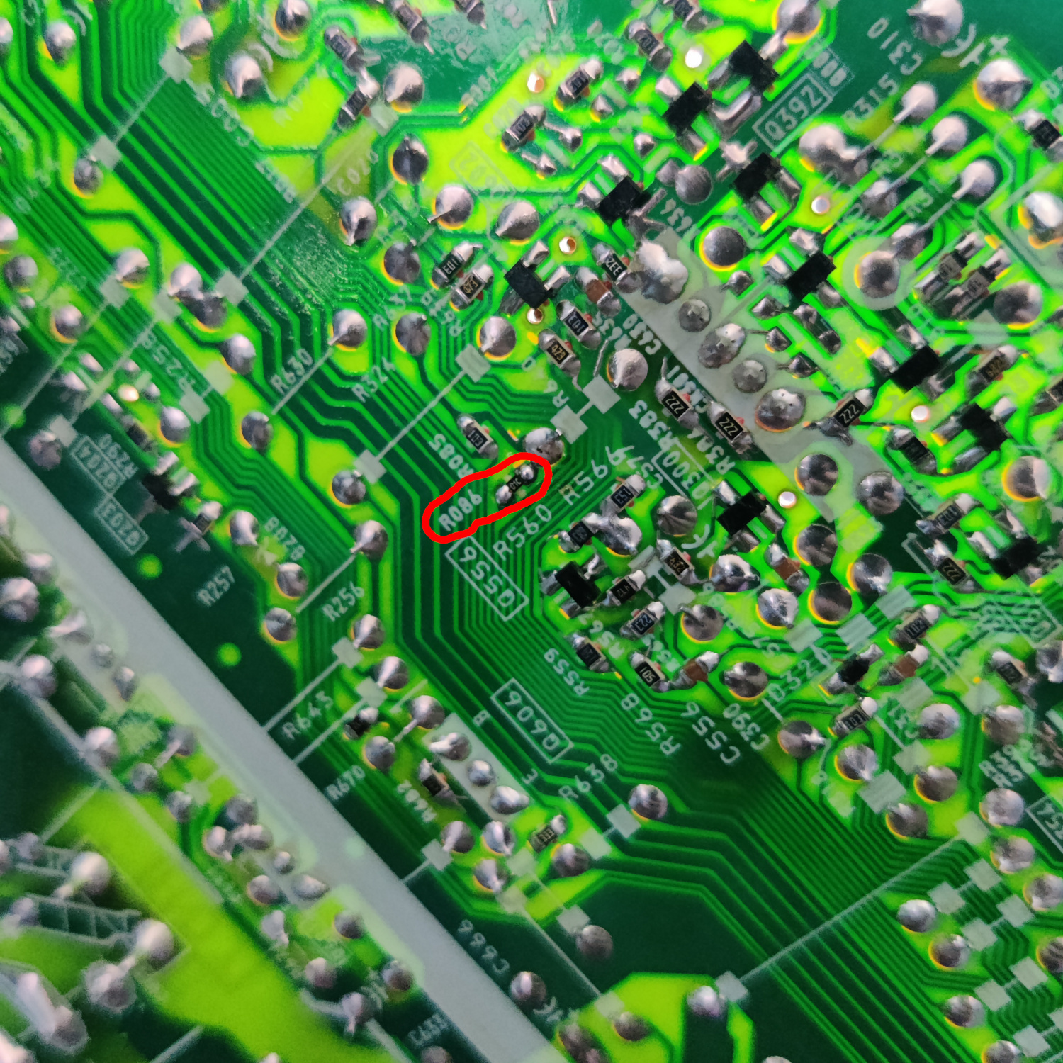
Next, still on the bottom of the board, locate the spot for R086 near Q556 and populate it with a 10K resistor.
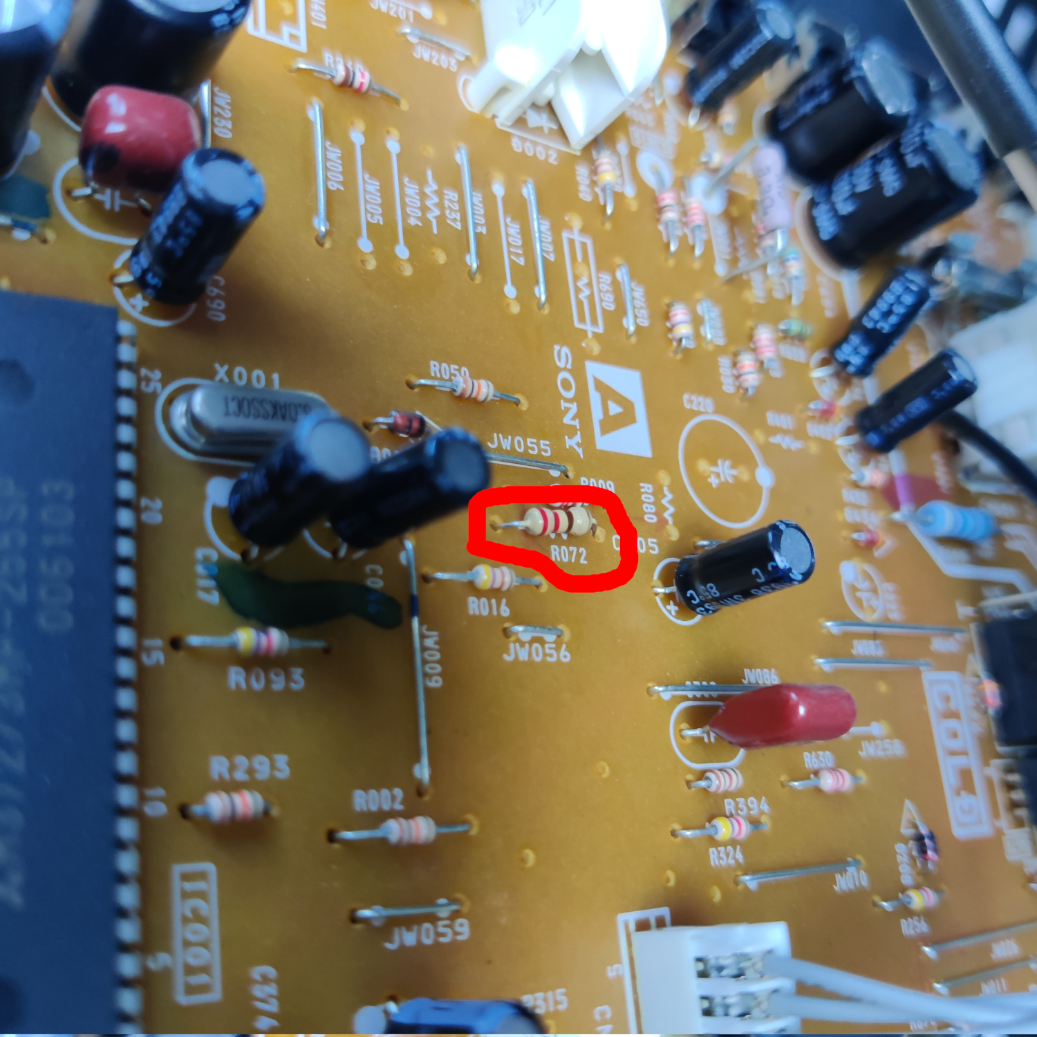
Then, on the top of the board locate the spot for R072 near IC001 and populate it with a 220 Ohm resistor.
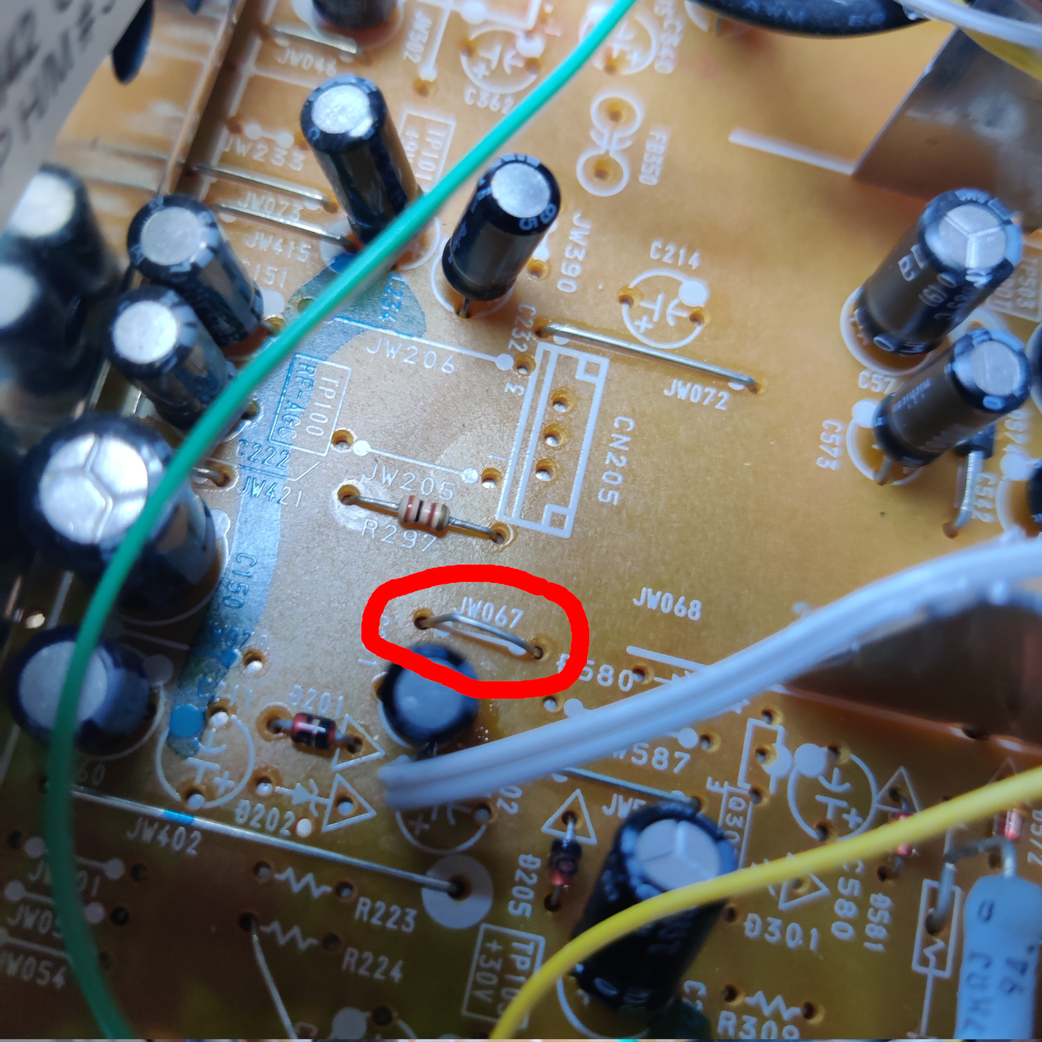
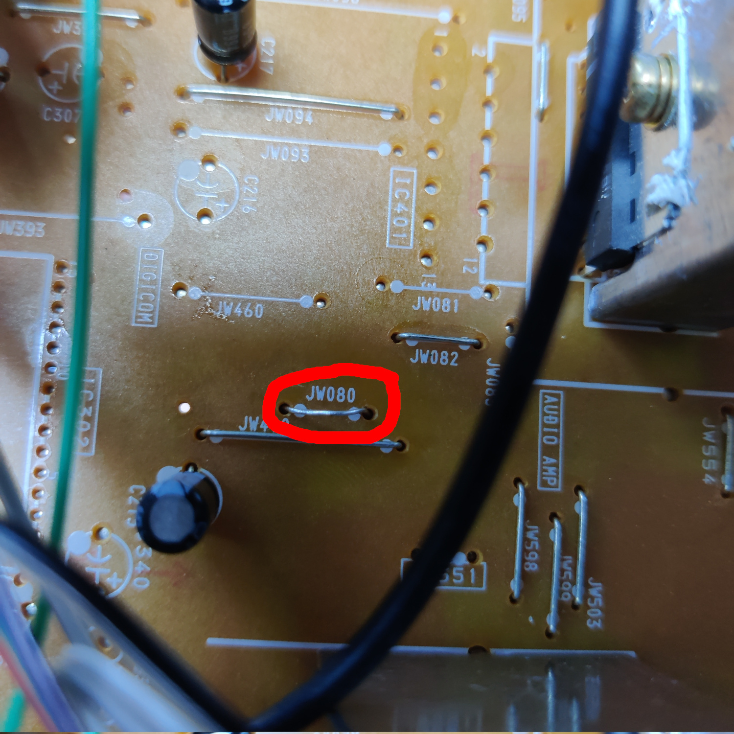
Finally, locate the spots for jumpers JW067 near CN205 and JW080 near IC401 and populate those with jumper wires.
All this was to restore the ability for Video 2 to have audio.
Then we need to add a few components for connecting Chroma from S-Video to the jungle chip.
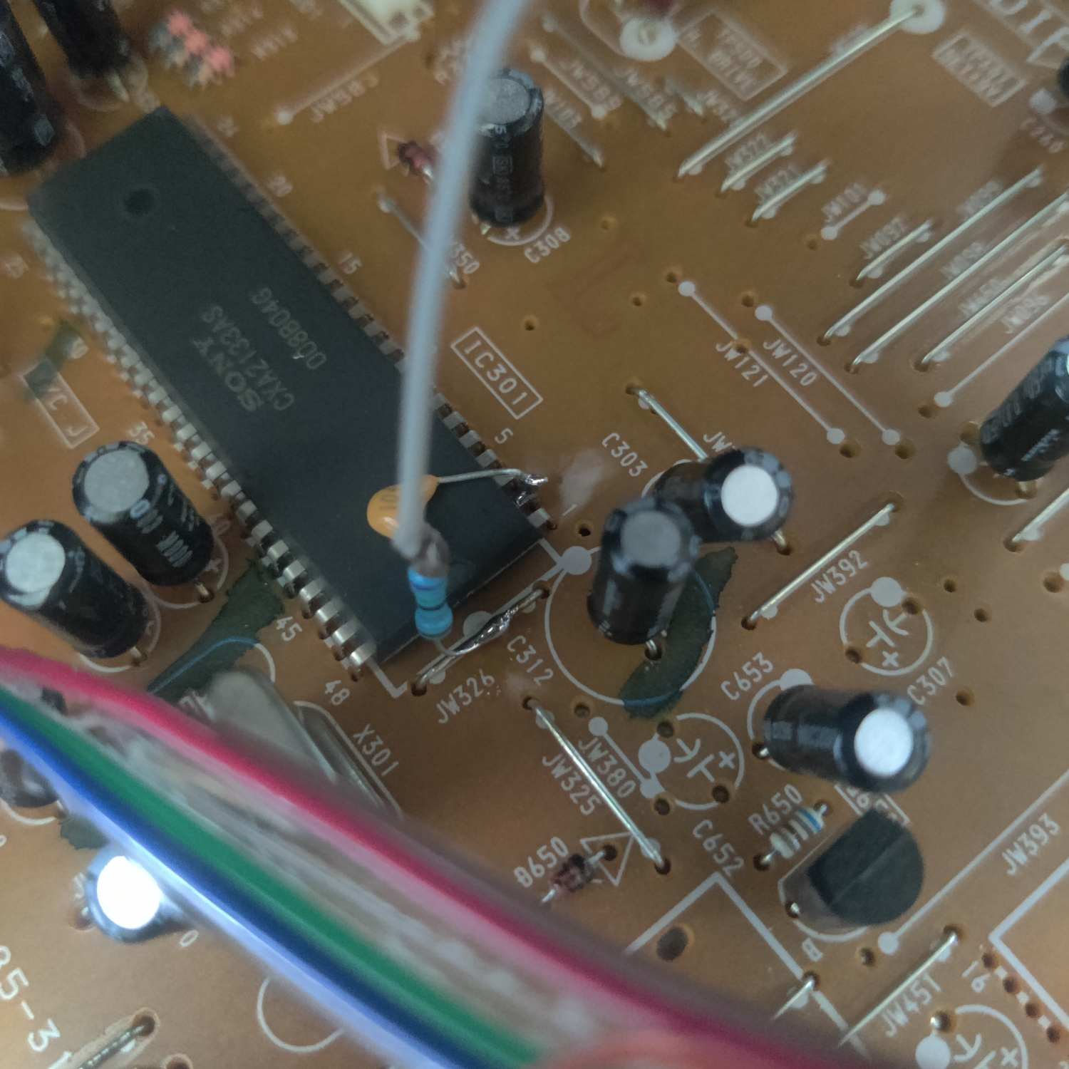
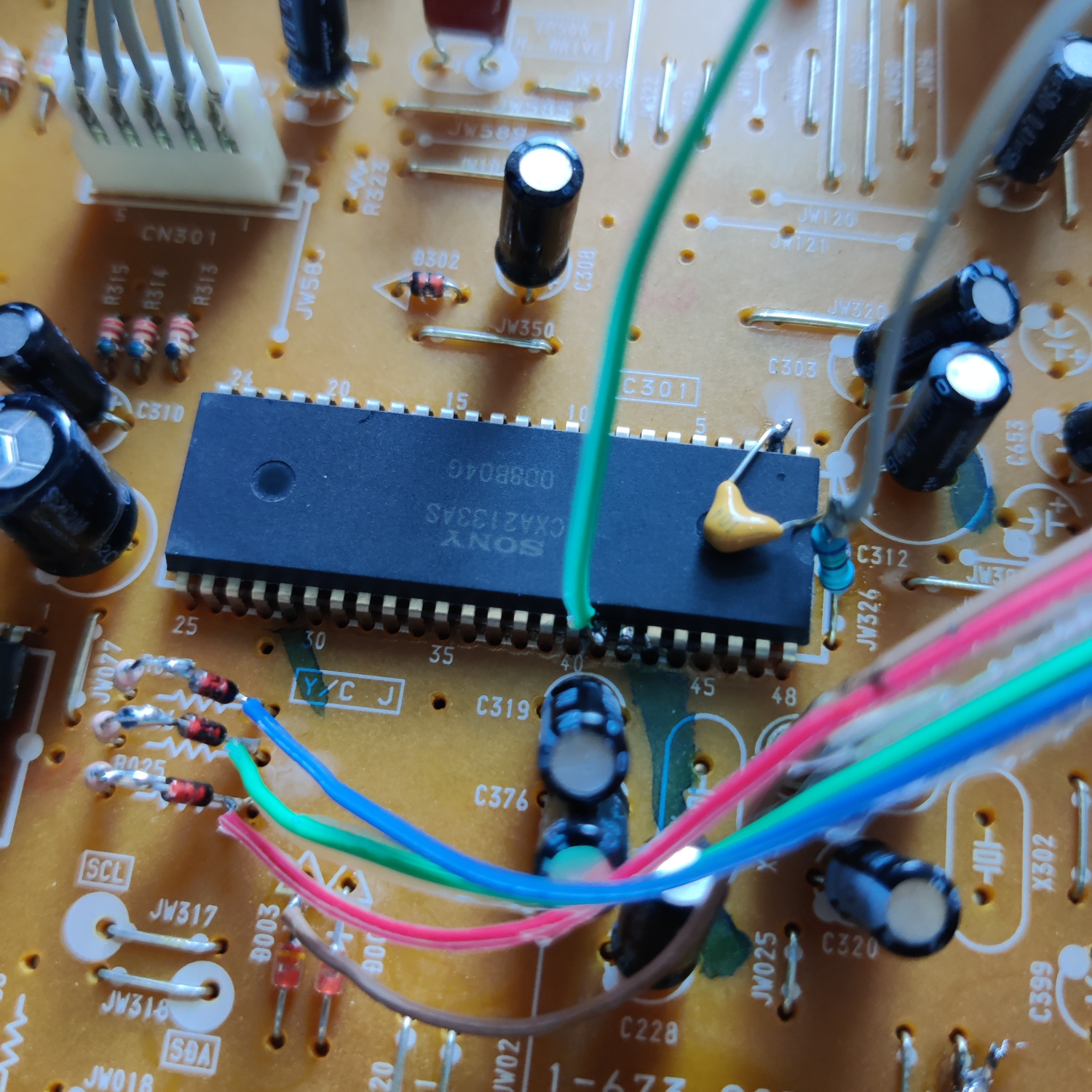
Connect one side of a 100nF ceramic capacitor to pin 2 of IC301. Connect the other side of that capacitor to a 75 Ohm resistor and to a wire that will go to the Chroma input from the S-Video jack. Connect the other side of the 75 Ohm resistor to ground (I used JW326 next to IC301).
Next we need to do a few things to be able to connect Luma (Y) of the S-Video input.
Lift the negative (-) side of C200 and connect a 75 Ohm resistor to it, as well as a wire that will go to the Y side of the S-Video input. Connect the other side of the 75 ohm resistor to ground, I used the empty hole on the left side of the spot for R224 when viewing the label from the back of the board. It’s close to C200 which is why I used it. See the photo below.
Connect a wire to JW024 which will be the ground wire for the S-Video input jack. See photo below.
Doing this disconnects composite video, so we need to connect that to the Video 2 input on the jungle chip.
In the hole that was left over from lifting C200 (the negative side of C200), insert the negative lead of a 10uF capacitor. Connect the other side of that capacitor to a wire that will go to the jungle chip IC301. See photo below.
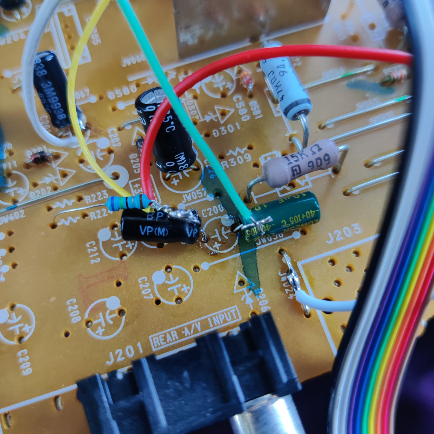
Finally, take the wire that was soldered to the other side of the capacitor inserted into the negative hole of C200 and connect it to pin 41 of IC301. (The other wires in the photo below are from the RGB mod).
This will send Composite video to the Video 2 input.
Finally, if you want stereo audio, a couple resistors need to be added.
Lift the negative (-) lead of C201. Insert a 1K resistor into the hole from the lifted capacitor lead and connect the other side to the lifted capacitor lead. Then connect another 1K resistor to the lifted capacitor lead and connect a wire to the other end of the resistor. This wire will go to the added audio input RCA jack. See photo below (the two additional white/grey wires are from the RGB mod).
Step 3: Install S-Video and Additional Audio Jack
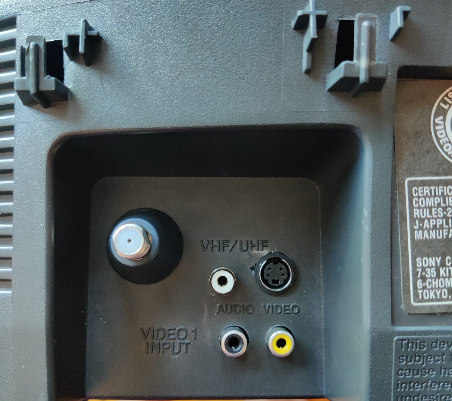
All that’s left is to install the new input jacks. Drill holes above the existing composite video and mono audio jacks to install your S-Video and additional audio jack.
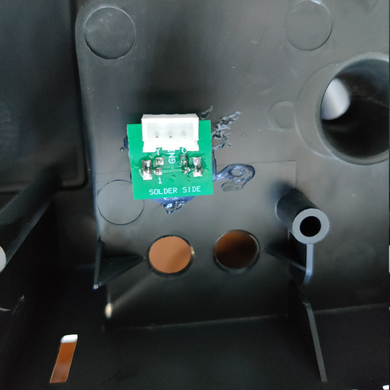
For S-Video I used this breakout board and a JST connector.
Finally, connect Y from S-Video to the wire soldered to the negative lead of the lifted C200, connect C from S-Video to the 100nF capacitor that is connected to IC301 pin 2 (connect to the lead that is soldered to the 75 Ohm termination resistor), and connect ground from S-Video to the ground wire soldered to JW024.
If you added the resistors to take in stereo audio, connect the other side of the additional 1K resistor that was soldered to the negative lead of C201, to the center lead of the audio input RCA jack, and solder the ground of that jack to a suitable ground.
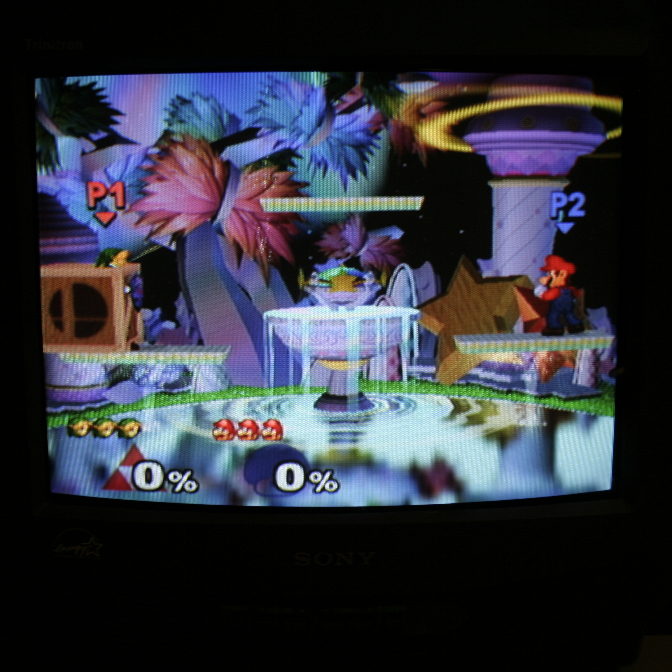
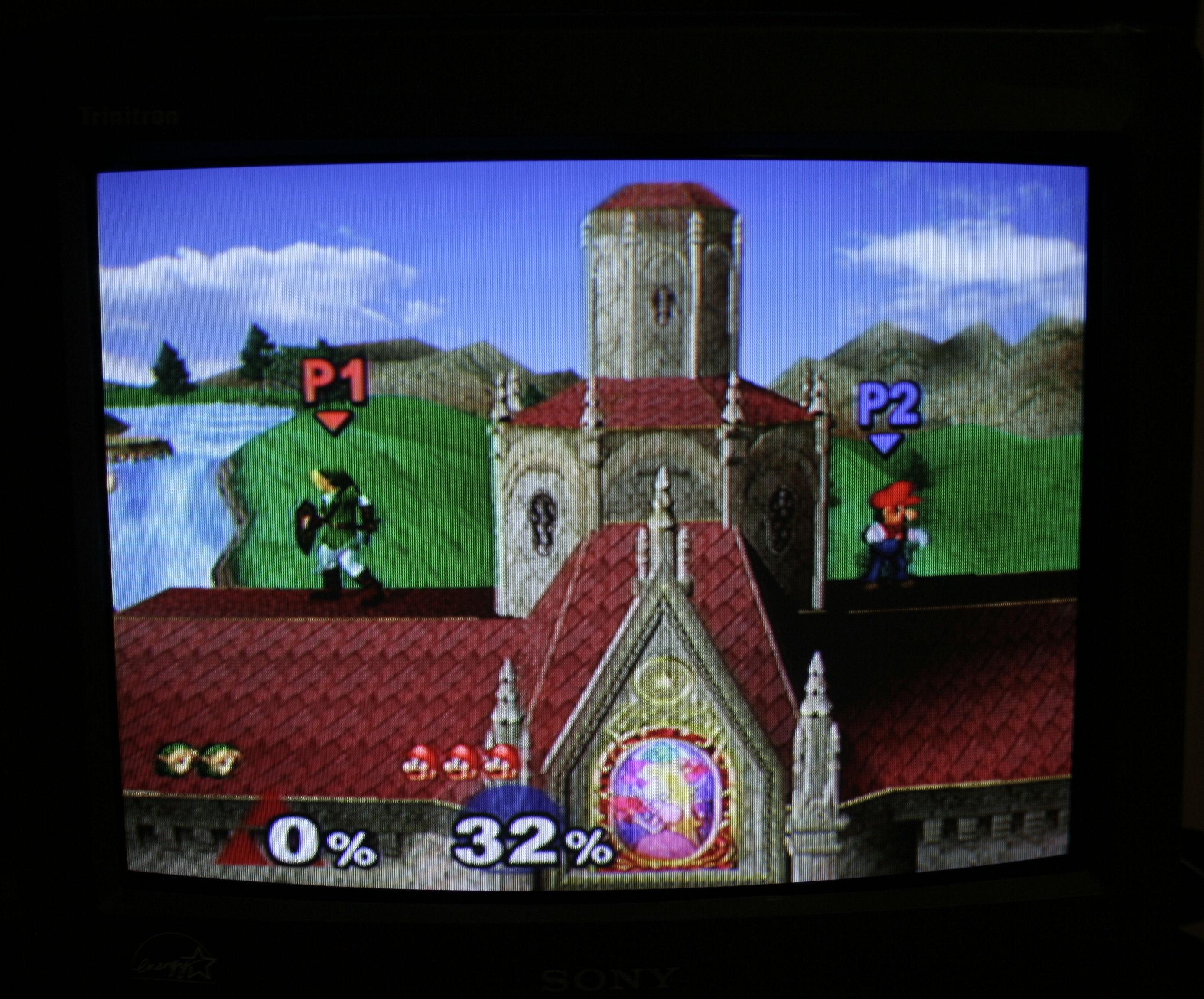
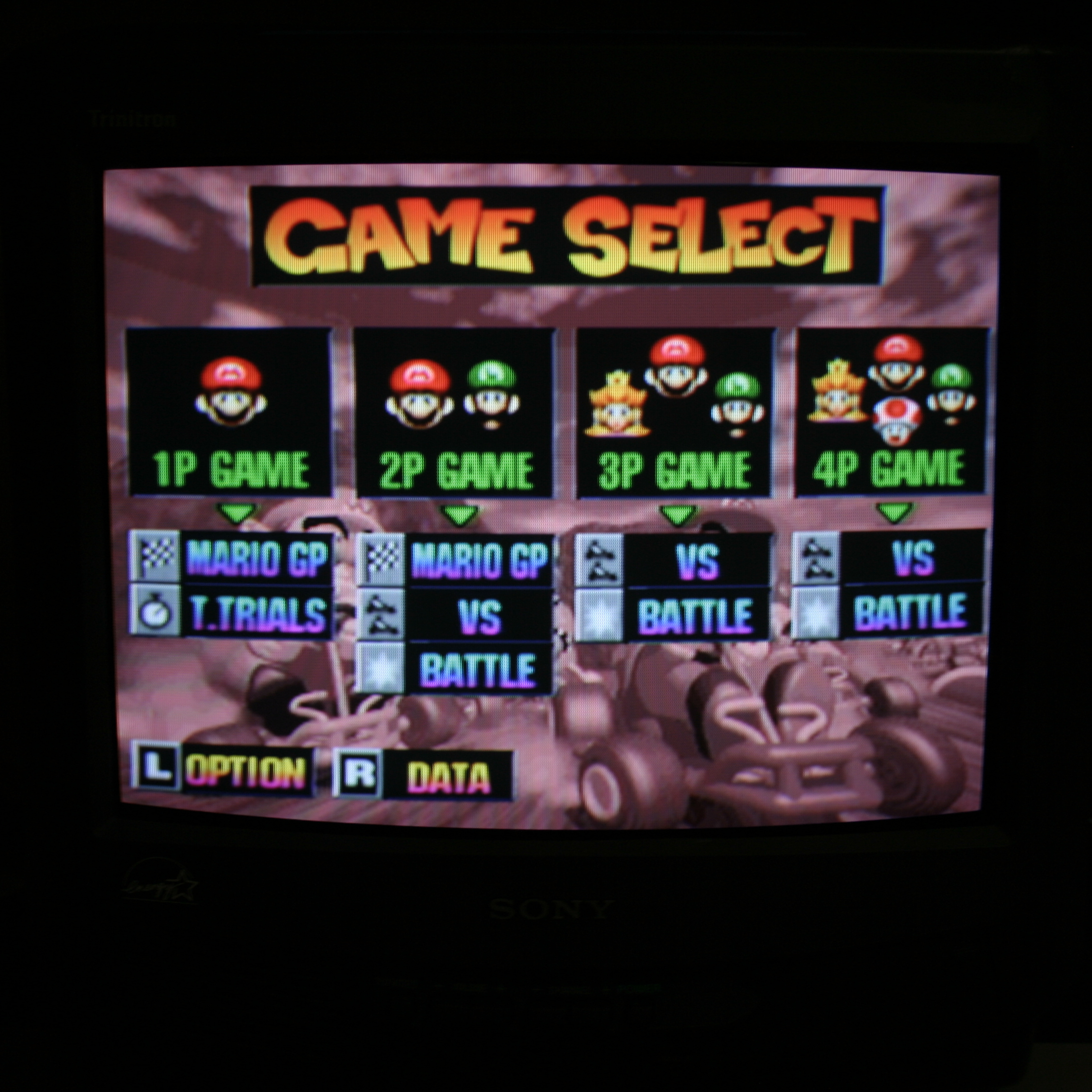
That’s it! You should now get S-Video on Video 1, Composite on Video 2, and they should both get audio from the same RCA jacks (unless you opted for them to have separate audio inputs and added the necessary input jacks).
S-Video Photos
This article is also hosted on Sunthar.com
Back to top