Sony KV-13M42 - RGB and Component Mod
This guide will cover how to RGB BNC/SCART mod and Component RCA mod the 13” Sony KV-13M42 BA-4D Chassis.
First I’ll cover the Component mod and then the RGB mod.
The Component Mod
I installed the mod using Sunthar’s BA-4D component guide, which you can see here for additional references.
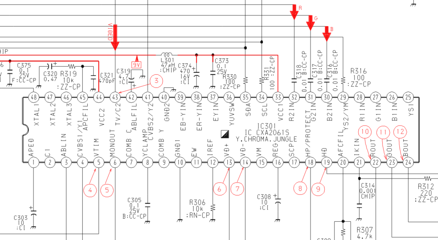
Both mods will be focused on the Jungle chip, IC301. Be sure to discharge the CRT before working on it!
To install the component mod, the following needs to be done:
- Connect Y input to the composite input and to pin 37 of IC301 with a 0.01uF (10nF) inline capacitor
- Connect 75 Ohm terminated PR input to pin 38 of IC301 with a 0.01uF (10nF) inline capacitor
- Connect 75 Ohm terminated PB input to pin 39 of IC301 with a 0.01uF (10nF) inline capacitor
- Connect a switch to send 5V to pin 36 of IC301 with a 220 Ohm resistor, a 1N4148 diode, and a 1K resistor inline (this turns on and off Component input).
NOTE: You do not need to 75-ohm terminate Y because it is going to be connected to the composite input line which is 75-ohm terminated.
Nothing is connected to these IC301 pins on this model so there are no components to remove.
The following graphic shows the wiring for this mod.
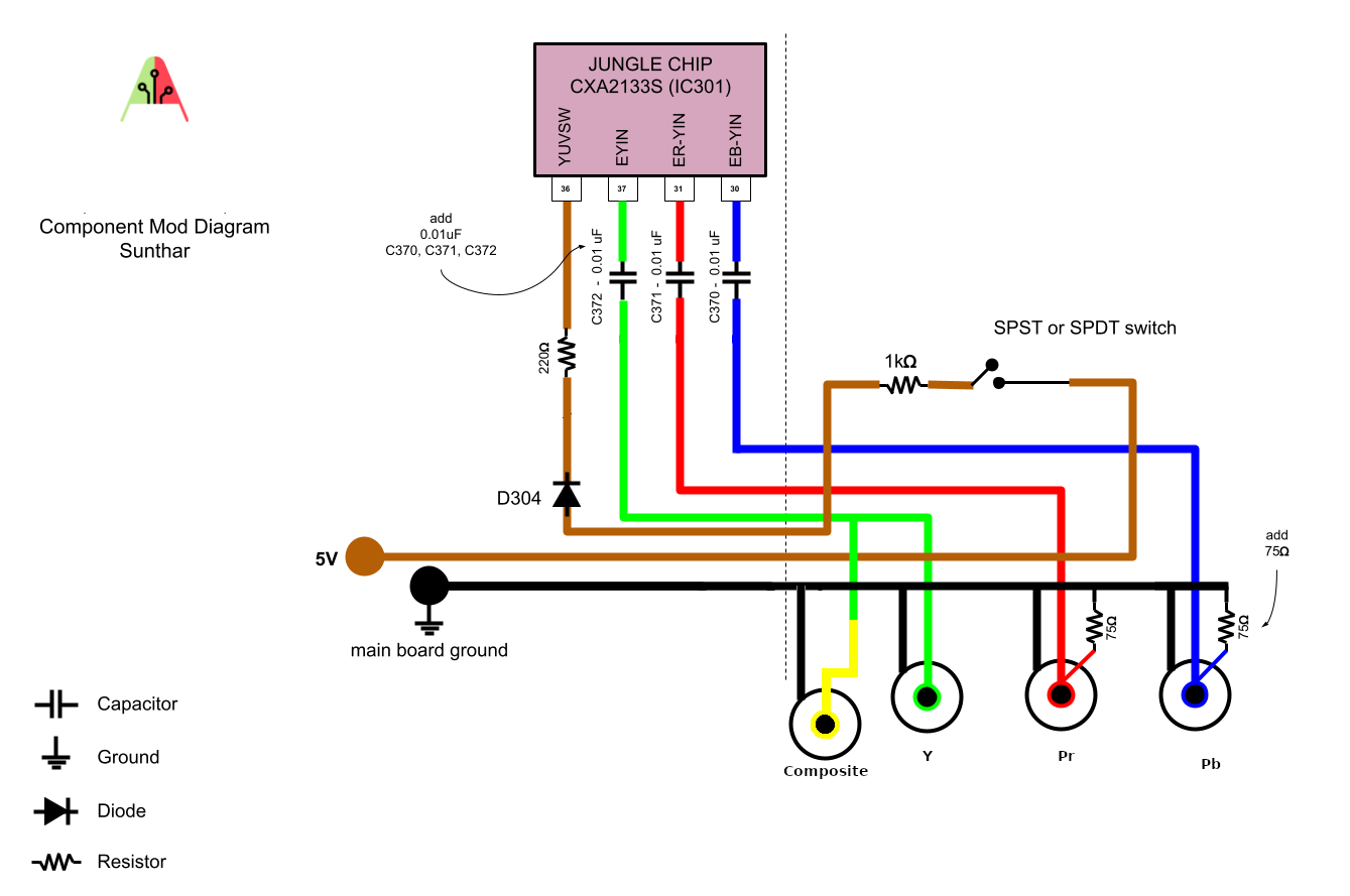
Since this guide also covers the RGB mod with BNC connectors, I used a SPDT switch on the 5V line to select between Component, RGB and Composite inputs.
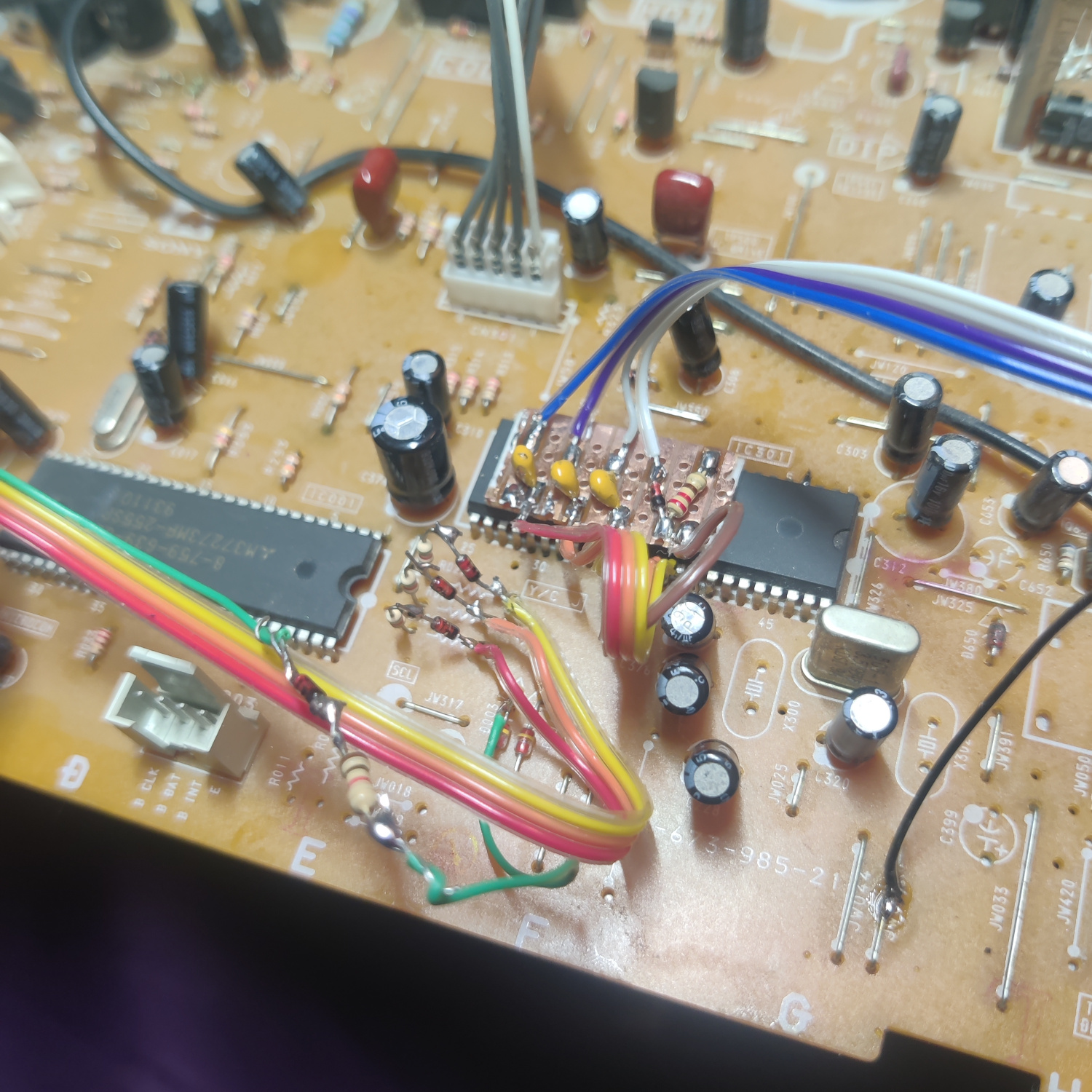
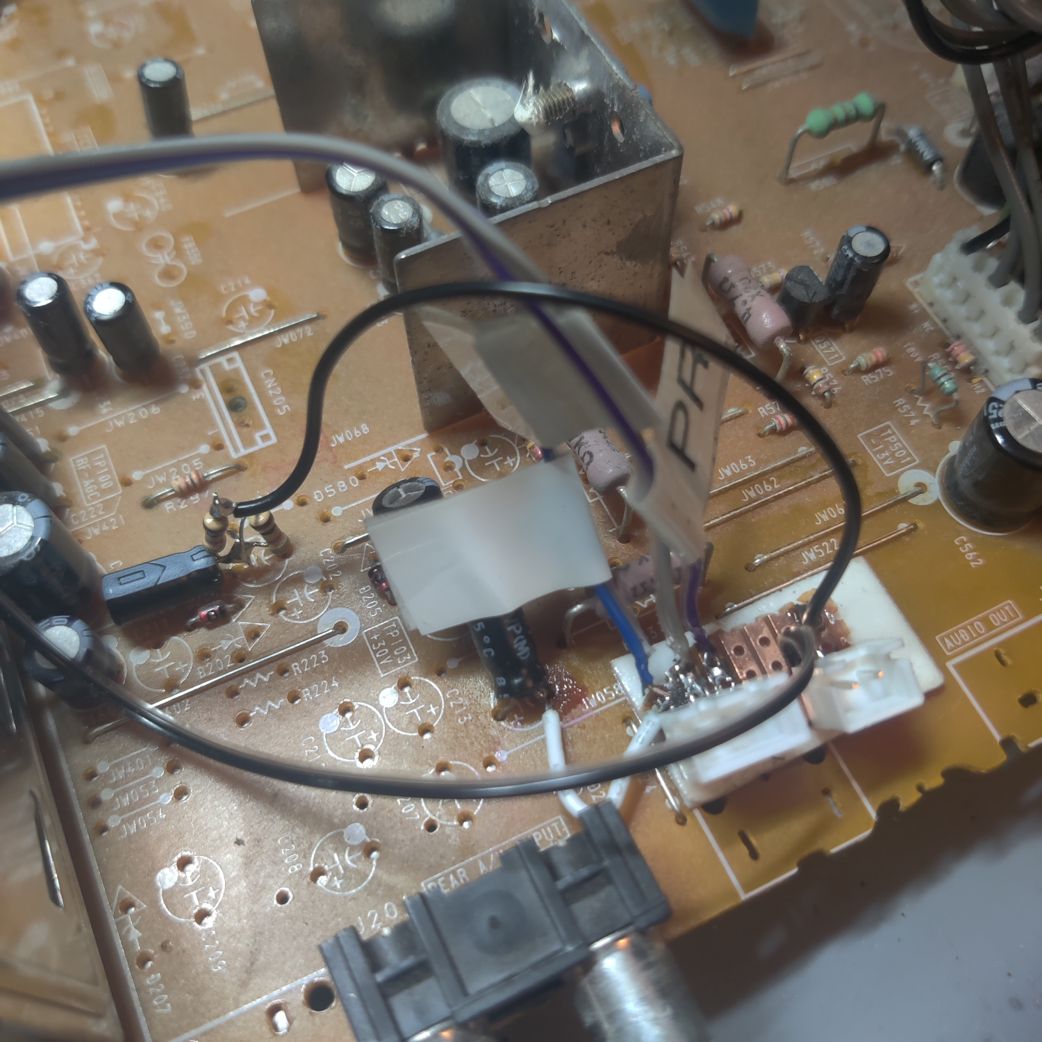
To make the install easier, I used a small prototyping PCB to hold the parts and solder the wires to.
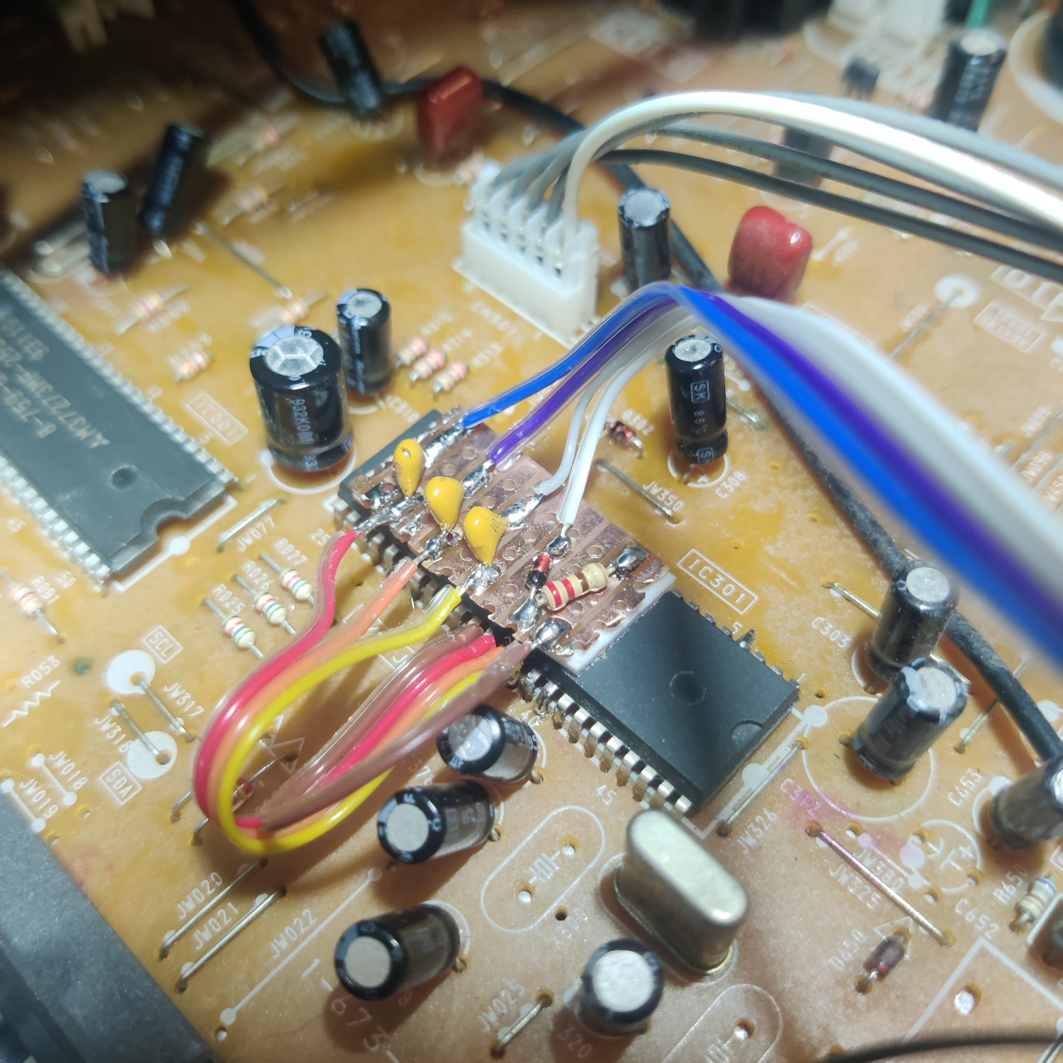
As you can see, the capacitors, the 1N4148 diode and the 220 Ohm resistor are on the board.
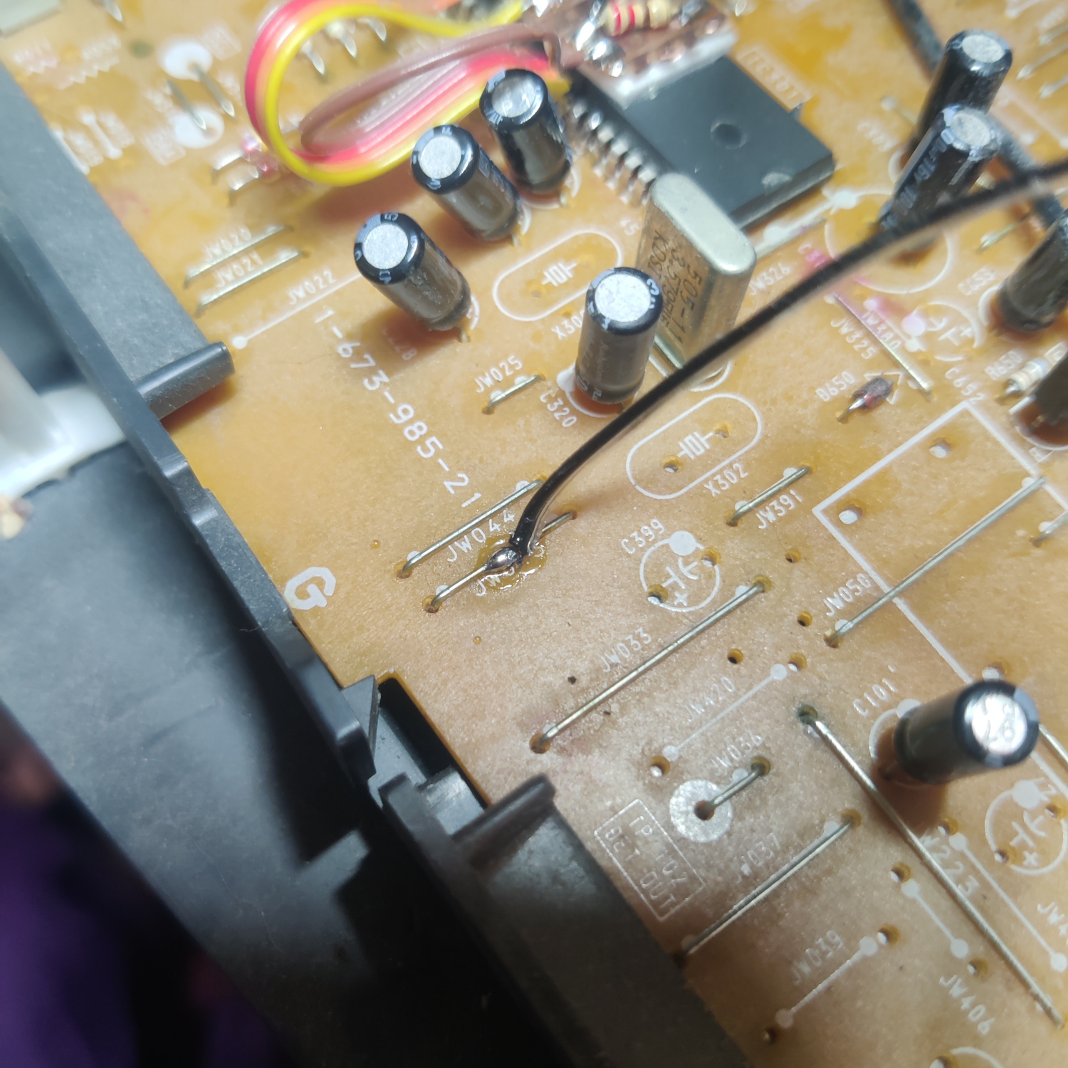
I got 5V from the positive side of C651. The 1K resistor I put inline on this wire.
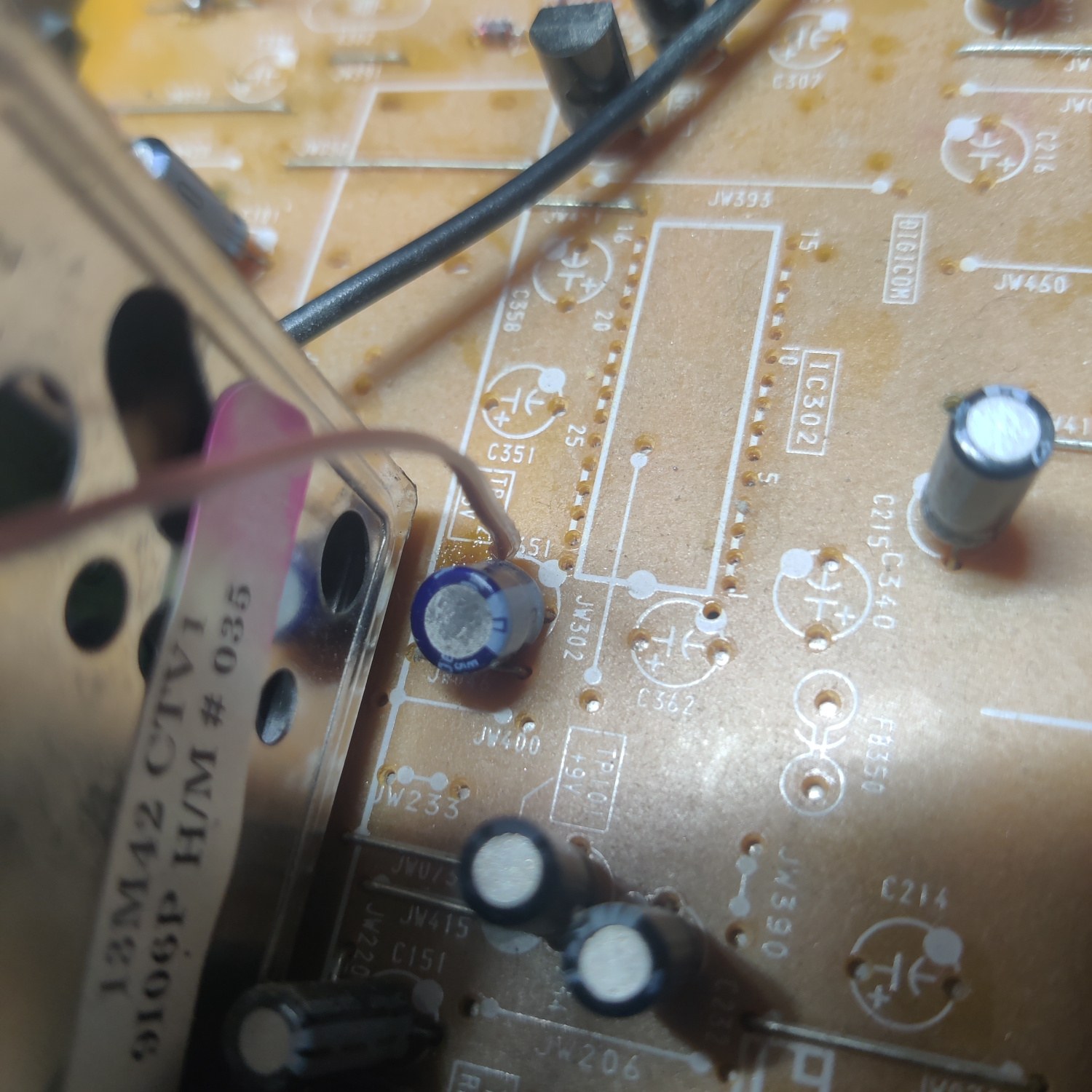
And I got ground from this jumper near the jungle chip.
For the RCA connectors, I drilled holes above the composite input.
I used JST connectors between the RCA connectors and the mainboard to allow the shell of the set to be removed.
For the switch, I drilled a hole in the front. The 5V source is connected to the middle of the SPDT switch and the wire out to the 220 Ohm resistor is connected one of the other legs.
And that’s all that needs to be done to get component video on this set. Turn the switch on and plug in a component video source to test it.
The RGB Mod
I installed the RGB mod using Sunthar’s BA-4D Chassis guide, which you can see here for additional references.
Step 1: Remove and Install Components
Open up your CRT and pull out the PCB. You may need to unplug some connectors to do so. Be sure to discharge the CRT before working on it!
On the bottom of the PCB, locate R087, R088 and R089 and remove them.
Next, on the top of the board locate R025, R026 and R027. Lift the side of these resistors that goes to the jungle chip IC301 (not the side that goes to the OSD chop IC001).
Insert the cathode (-) side of three 1N4148 diodes into the holes from the lifted resistors. Leave some of the lead of the diode exposed as this is where the RGB inputs are going to be connected as well. Solder the other side of the diodes to the lifted resistors.
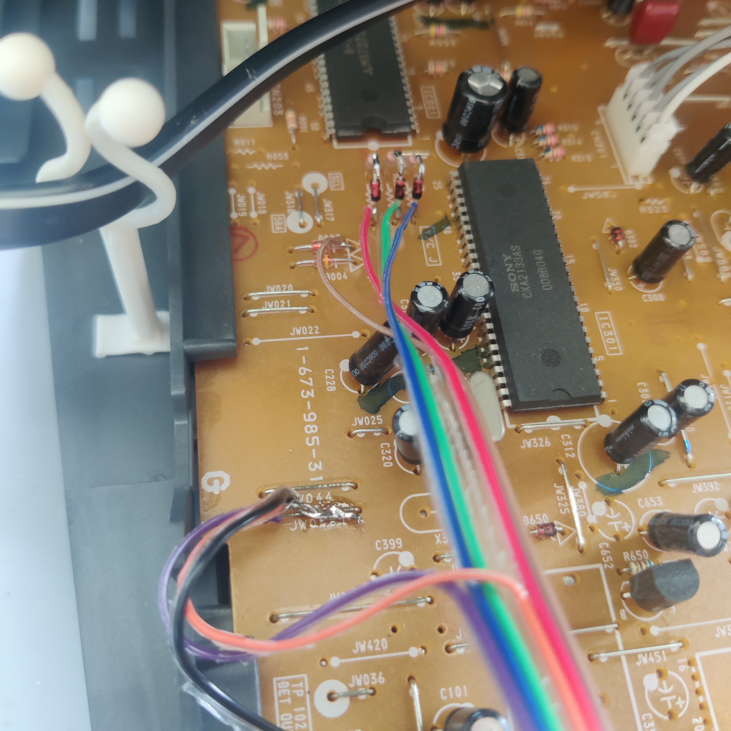
Connect 3 wires to the cathode (-) side of the diodes. These will go to the BNC/SCART connections for RGB.
Also connect a wire to the other pin on the SPDT switch used in the component mod to supply 5V to the blanking input. Wire a diode and a 1K resistor inline and connect this wire to the cathode (-) side of D003 as shown in the image above.
Step 2 (BNC): Connect Wires and Termination Resistors to BNC connectors
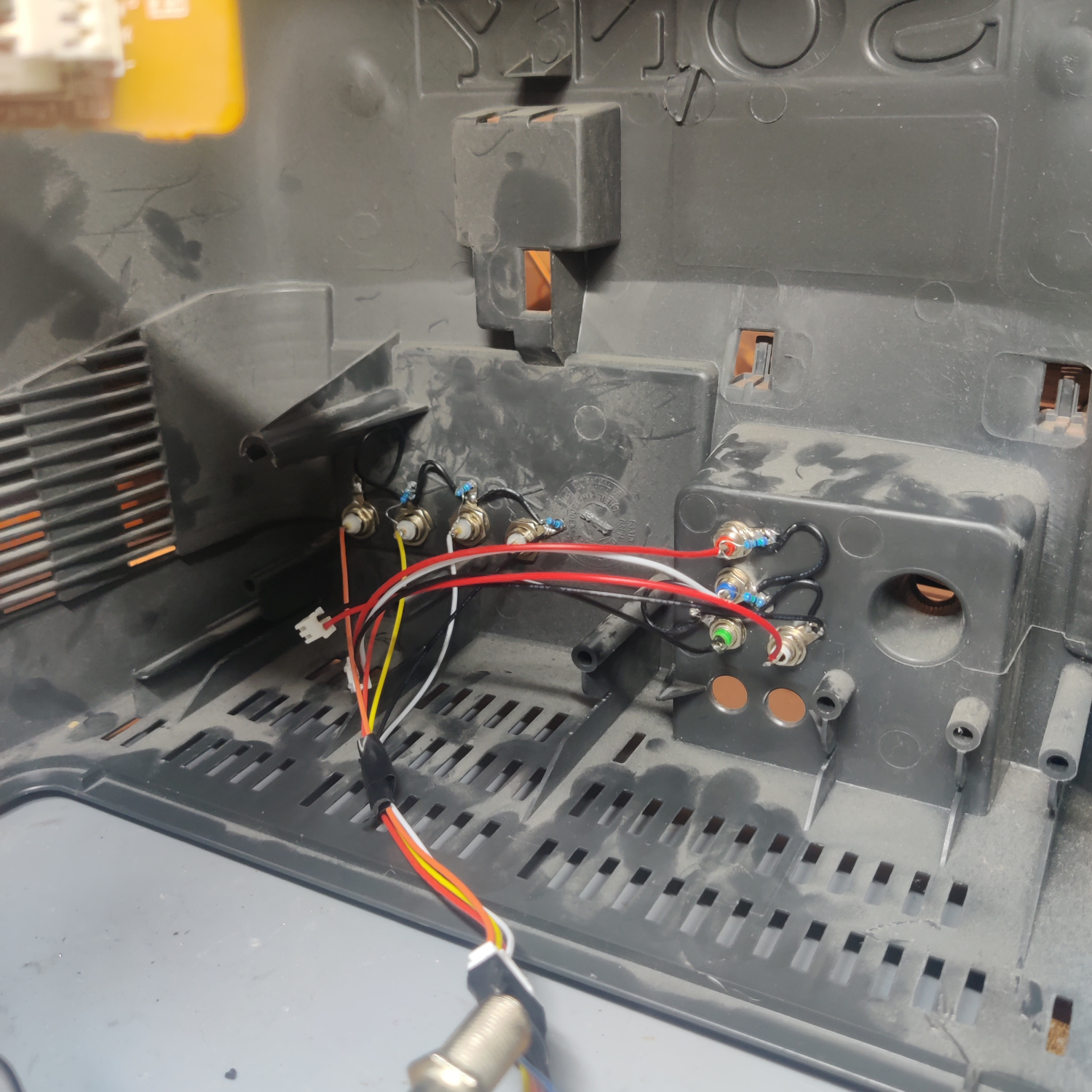
Take your BNC connectors (or RCA if you prefer) and drill holes in the shell to place them where you want. I chose on the right side of the back.
Mount the connectors on the shell and solder 75-ohm resistors from the center pins to the ground pins of the connectors to 75 Ohm terminate the RGB signals.
DO NOT 75 Ohm terminate the Sync connector as this is going to be connected to the composite input which is already 75 Ohm terminated.
Next we’ll connect all the wires, I Used a JST connector for all wires in between the BNC connectors and the main board to allow the shell to be removed.
Connect the grounds of the BNC connectors to each other and run a ground wire from the chassis to them.
Connect the RGB wires from the diodes that went into the lifted resistors’ holes, to the BNC connectors. R comes from R025, G from R026, B from R027.
Connect the Sync BNC input to the Composite video input on the main board. The negative (-) side of C200 is a viable location as well.
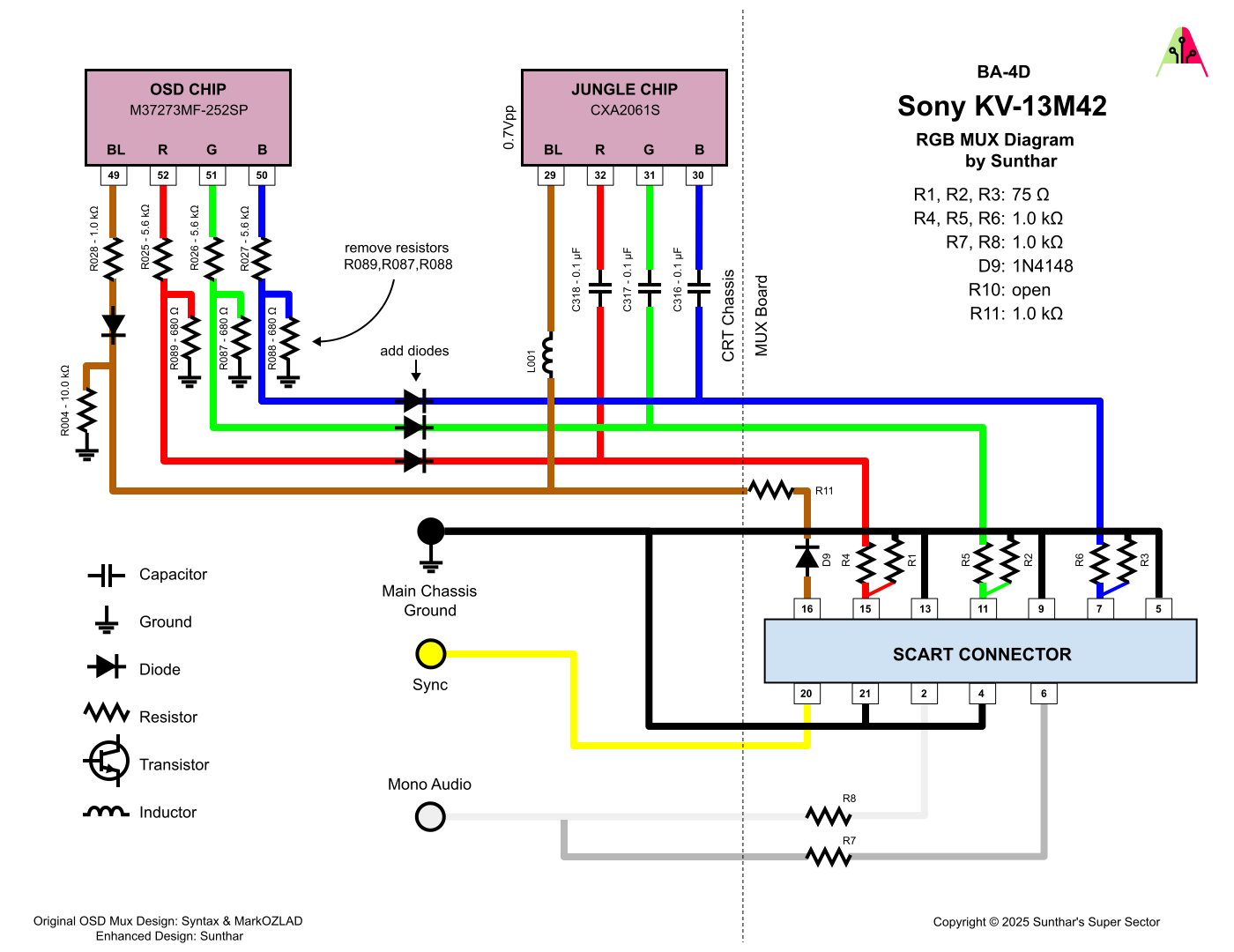
This image is for an RGB SCART mod, but it can be used as a reference for how everything is wired.
That is all you need to do for the RGB mod. You should now be able to set the SPDT switch to send 5V to RGB Blanking and see your RGB input on the screen.
If you did both the component and RGB mods, you should be able to switch between the two with the SPDT switch, but you cannot use both inputs at the same time.
Step 2 (SCART): Prepare and mount SCART port
You already wired up the RGB and blanking wires above, what’s left is audio and sync.
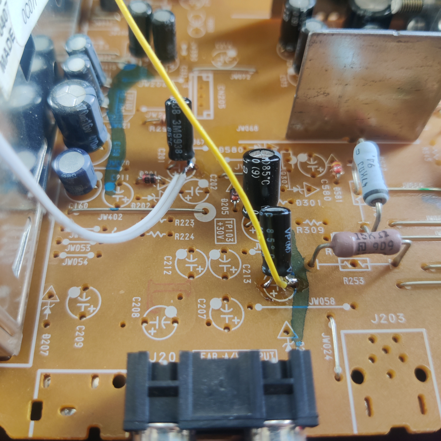
For audio, connect both L and R wires to the negative (-) side of C201.
For Sync, connect the yellow wire to the negative (-) side of C200, or to the center lead of the composite input jack.
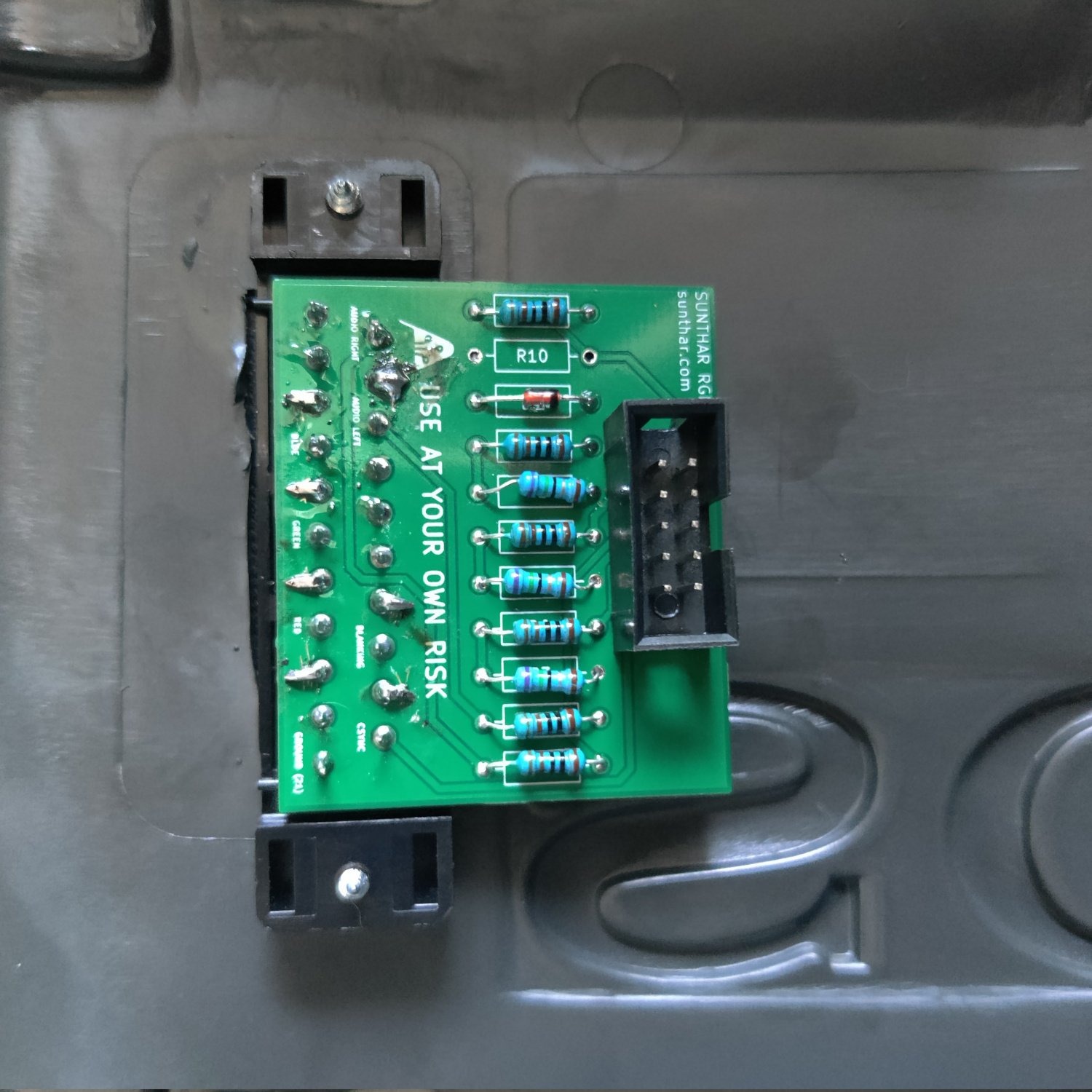
If you purchased a SCART port from Sunthar, you can follow the instructions on his site to prepare your SCART port.
CRT Database also has a great guide on creating a clean SCART connector setup, so check that out as well for more info.
TLDR info for making your own is:
- RGB inputs are 75 Ohm terminated then connect to your RGB wires from earlier with 1K Ohm resistors.
- The Blanking input is connected to a 1N4148 diode, then a 1K Ohm resistor to the blanking wire from earlier.
- Sync input is connected directly to the sync wire soldered earlier.
- Audio left and right are connected to the audio wires soldered earlier with 1K Ohm resistors inline.
- Ground is connected to the ground wires soldered earlier.
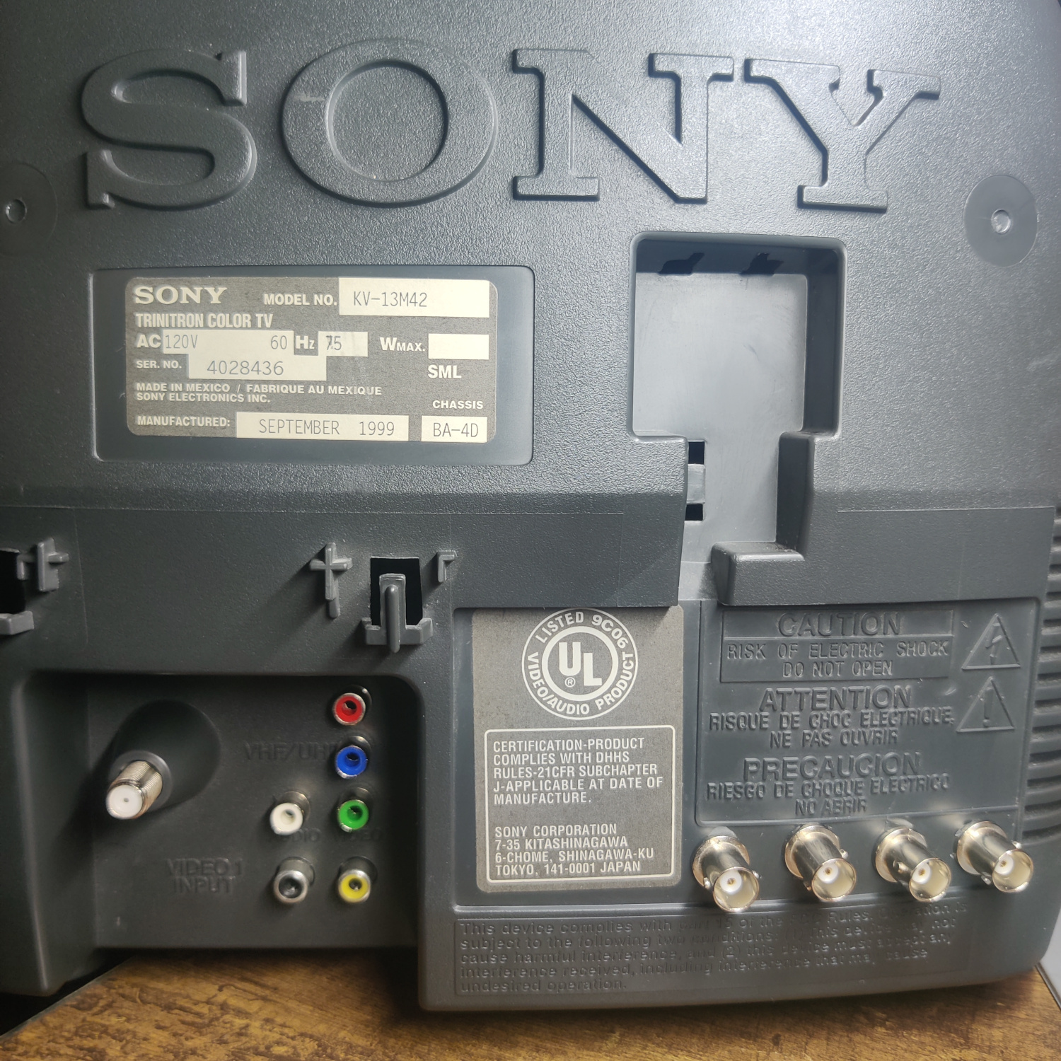
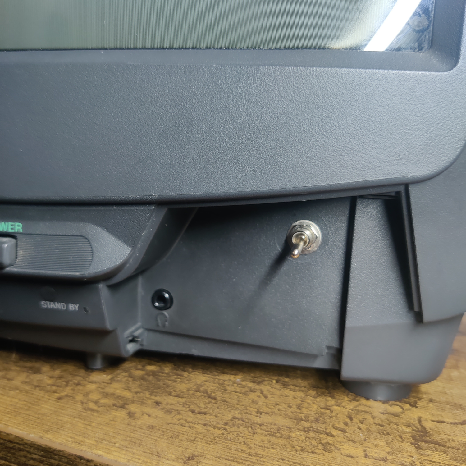
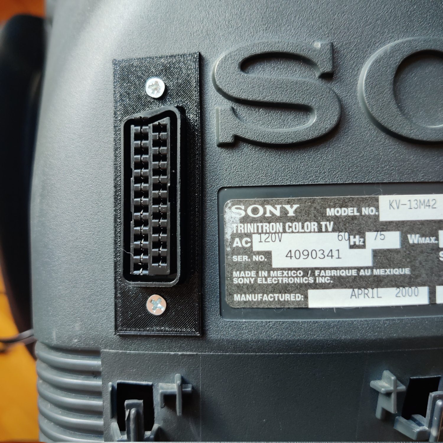
Next you’ll need to cut the hole for the port. I placed it above the stock inputs, next to the SONY logo. See the photo below.
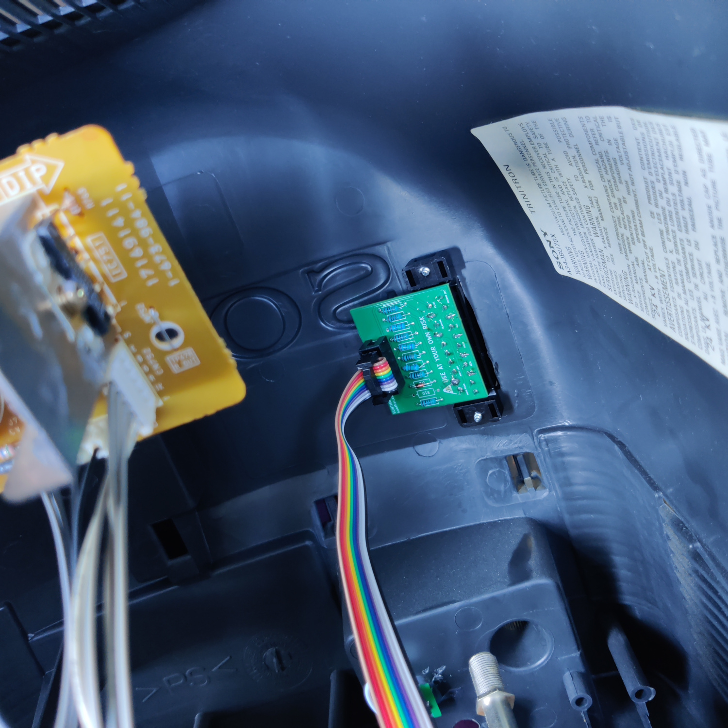
I used a 3D-printed SCART port panel to cover up any not-so-perfect cutting I did for the port.
To do the actual cutting I drew an outline of the port using the 3D-printed part and then used a sharp razor blade box cutter to cut the outline out. Then I drilled holes to screw into the port using some screws I found that were the right size to thread into the plastic of the SCART port. You can see the final results below. I modified the SCART port cover a bit to extend over some exposed portions of the case because I cut a bit too much plastic off for the port location I chose.
After you’ve mounted it and wired the port, you’re all set!
If you did both the component and RGB mods, you should be able to switch between the two with the SPDT switch, but you cannot use both inputs at the same time.
Step 3: Stereo to Mono Sum Input
If you want to be able to plug in stereo audio and have it summed to mono for this set, you’ll need to do the following:
- Lift the negative side of C201
- Insert a 1K resistor into the hole and solder it, then solder the other side to the lifted negative lead of C201
- Drill a hole for one RCA connector above the existing audio input RCA connector.
- Mount the RCA connector and connect the ground and center pins to a connector (I used JST) to allow the shell to be removed.
- Connect the ground wire to chassis ground.
- Connect the signal wire to a 1K resistor and connect the other side of this resistor to the lifted negative lead of C201.
The capacitor with the lifted lead on the left side of this image shows how this install looks.
You can see the additional audio input above the original one.
That’s it, you should now have stereo inputs that play as mono on the speaker.
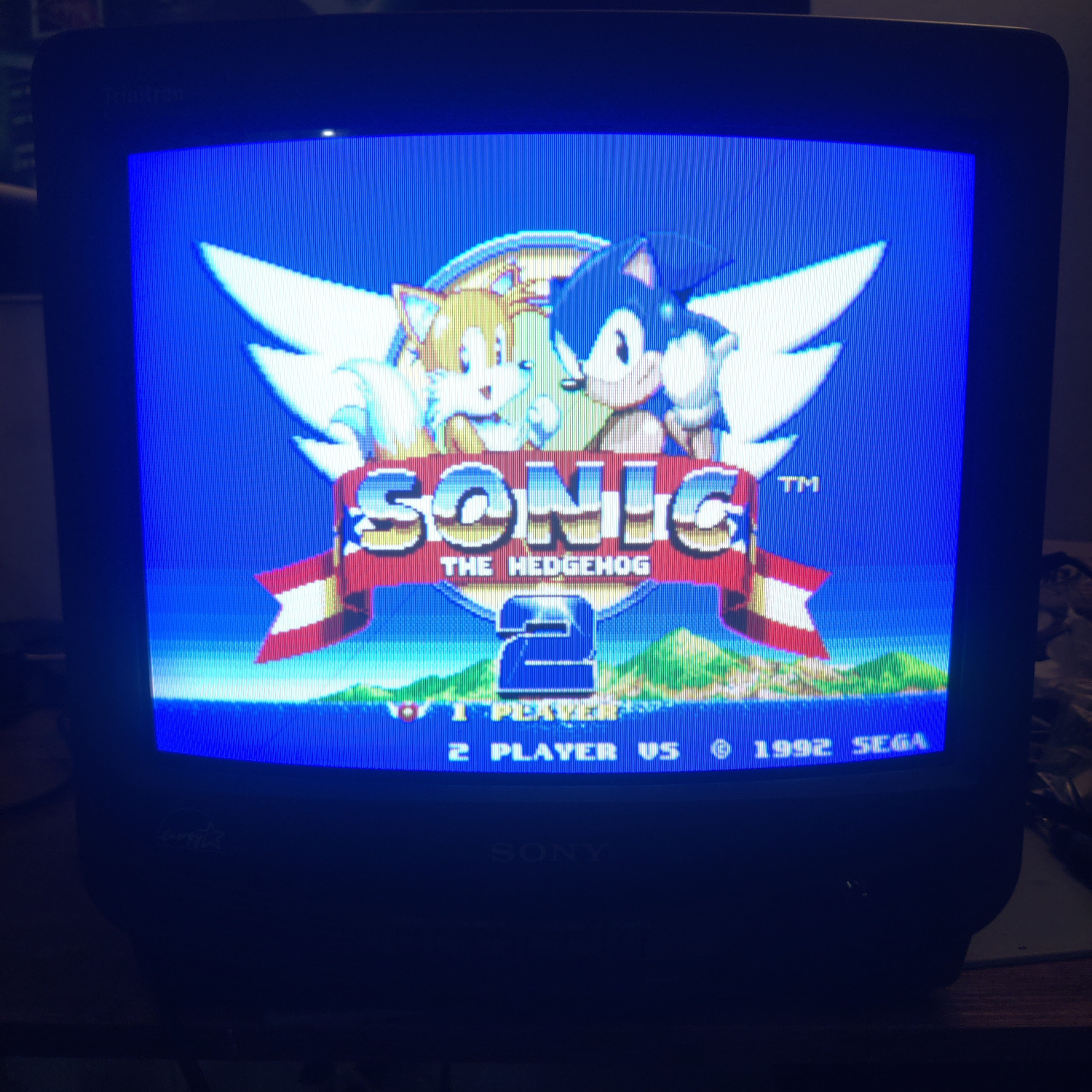
Comparisons
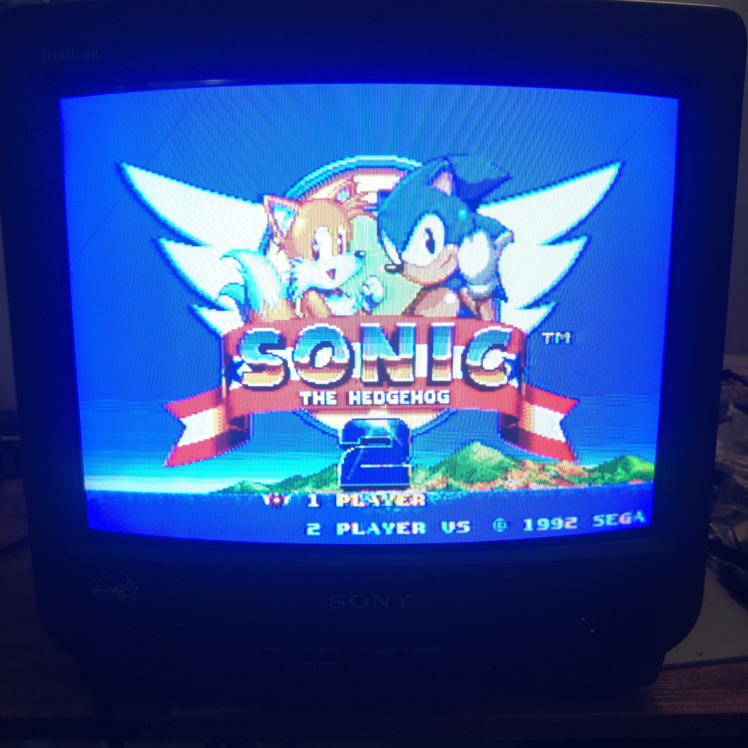
RGB
Component
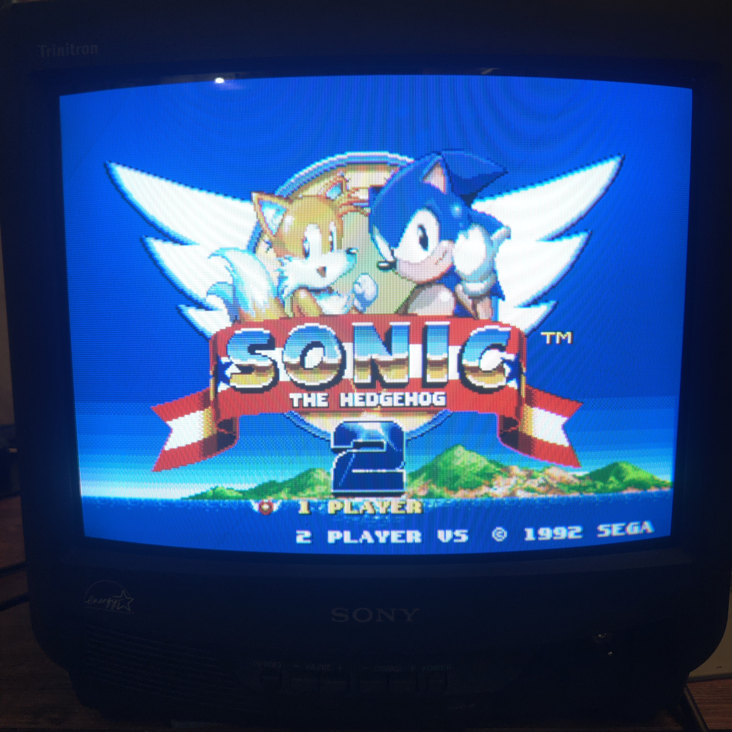
Composite
This article is also hosted on Sunthar.com
Back to top