Supersonic SC-2200 Component Video Mod
It is possible to Component mod this CRT by tying into the video and audio lines used by the DTV tuner addon board. This guide will cover how to do this.
NOTE: Doing this mod WILL DISABLE RF/DTV INPUT, so you will no longer be able to view regular TV channels or use RF as an input.
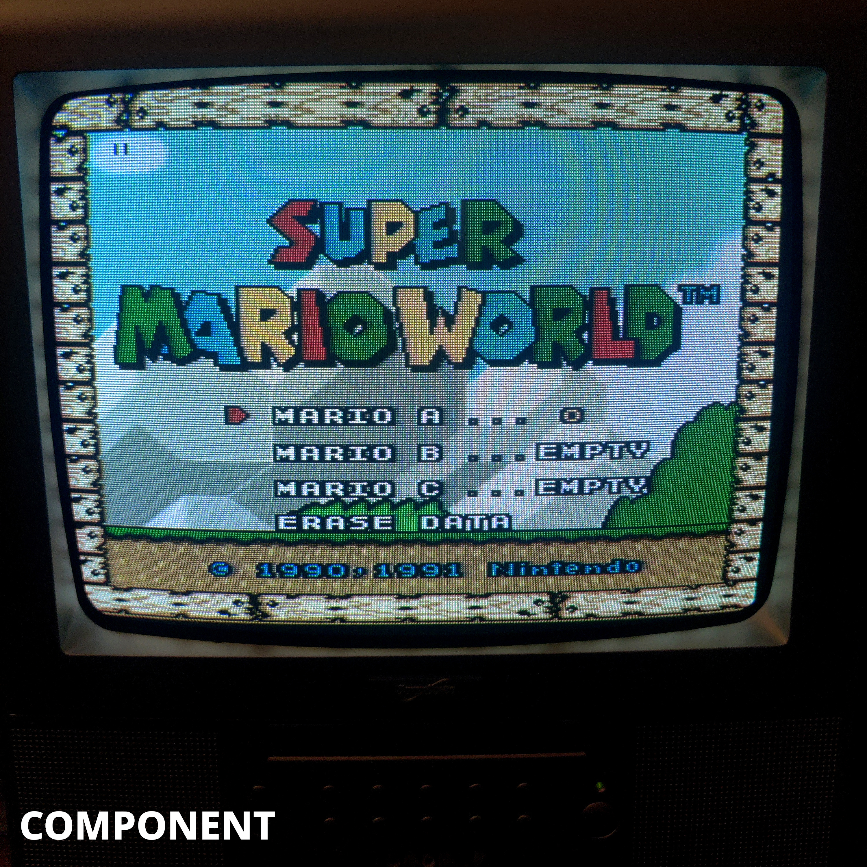
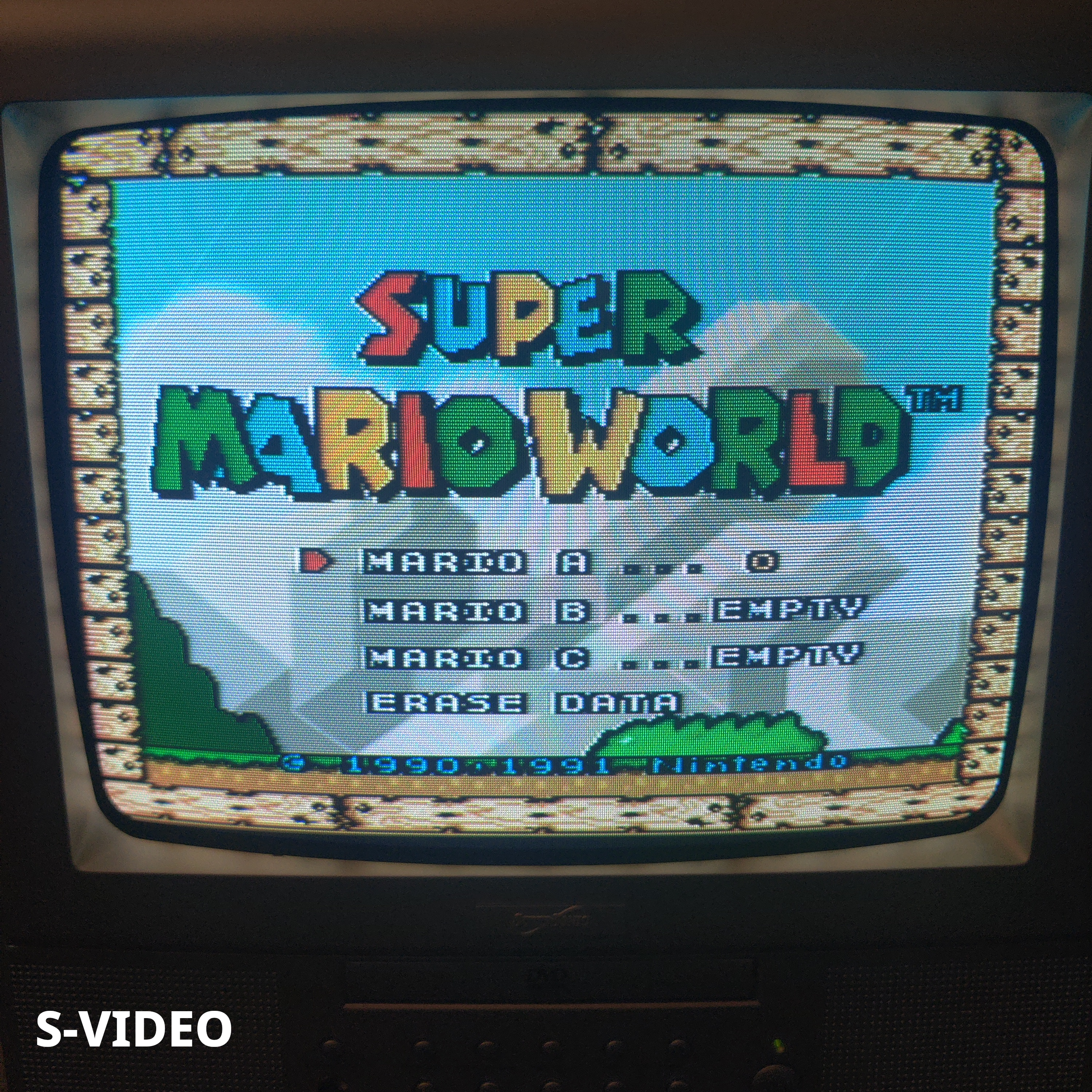
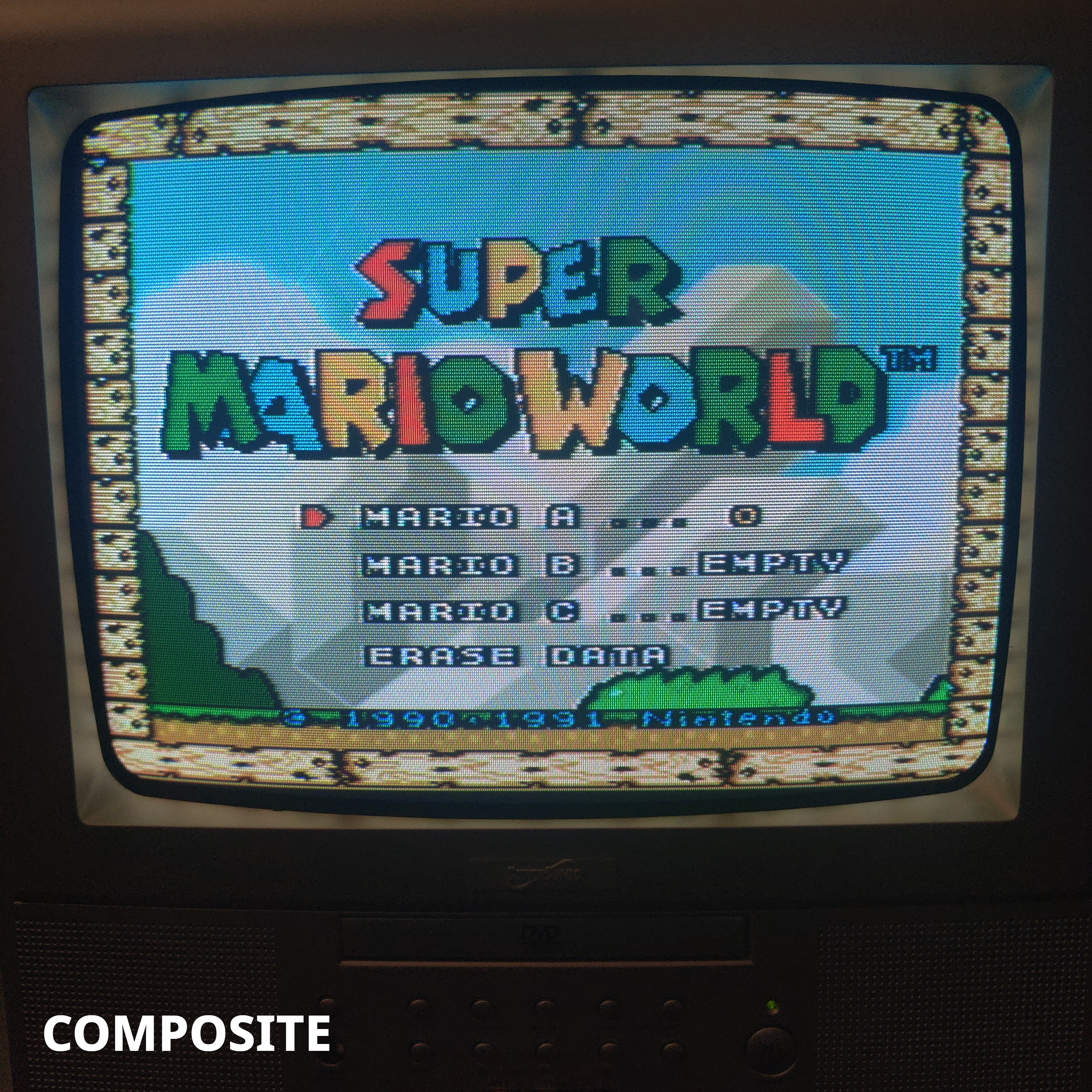
Prerequisites
You will need:
- 5x RCA jacks
- 3x 75 Ohm resistors
- Some wire
Step 1: Remove Components
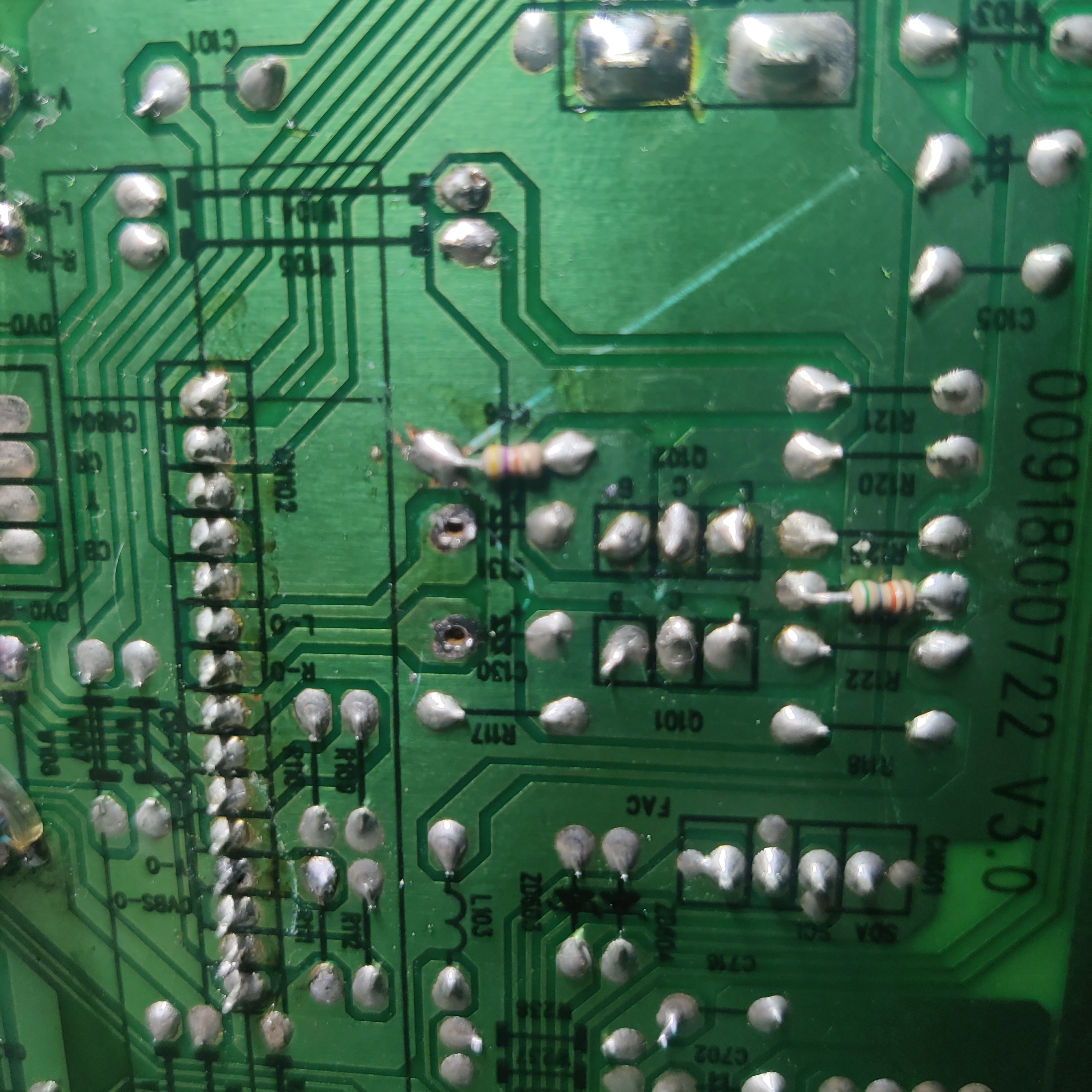
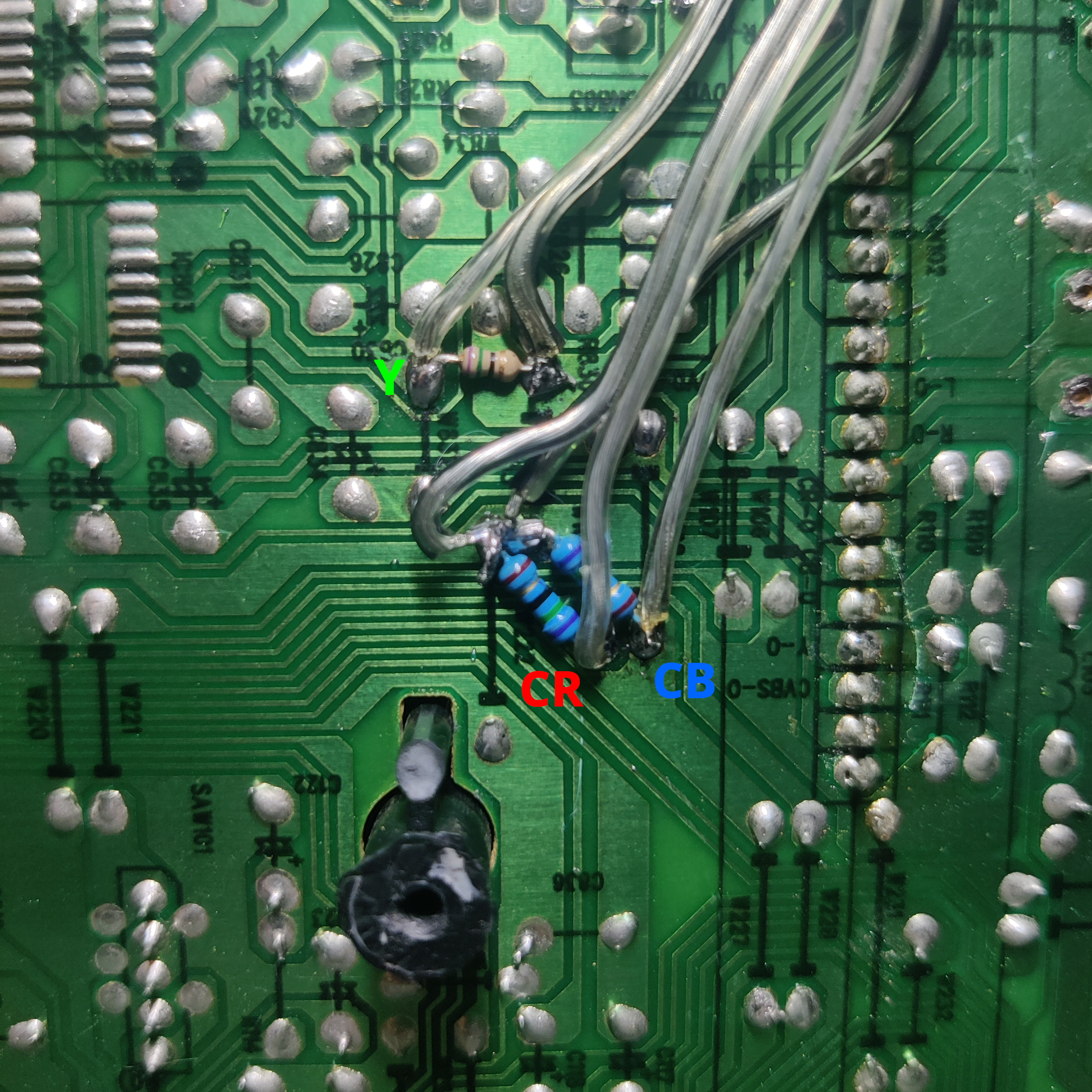
There are 3 jumpers that need to be removed in order to disconnect the DTV Tuner’s YCbCr outputs from the inputs to the Jungle Chip.
They are W833(Y), W108(Cb), and W109(Cr). The side of the Cb and Cr jumpers closest to, and the side of the Y jumper farthest away from, the Jungle chip on the underside of the PCB is where we will inject our external Component signals.
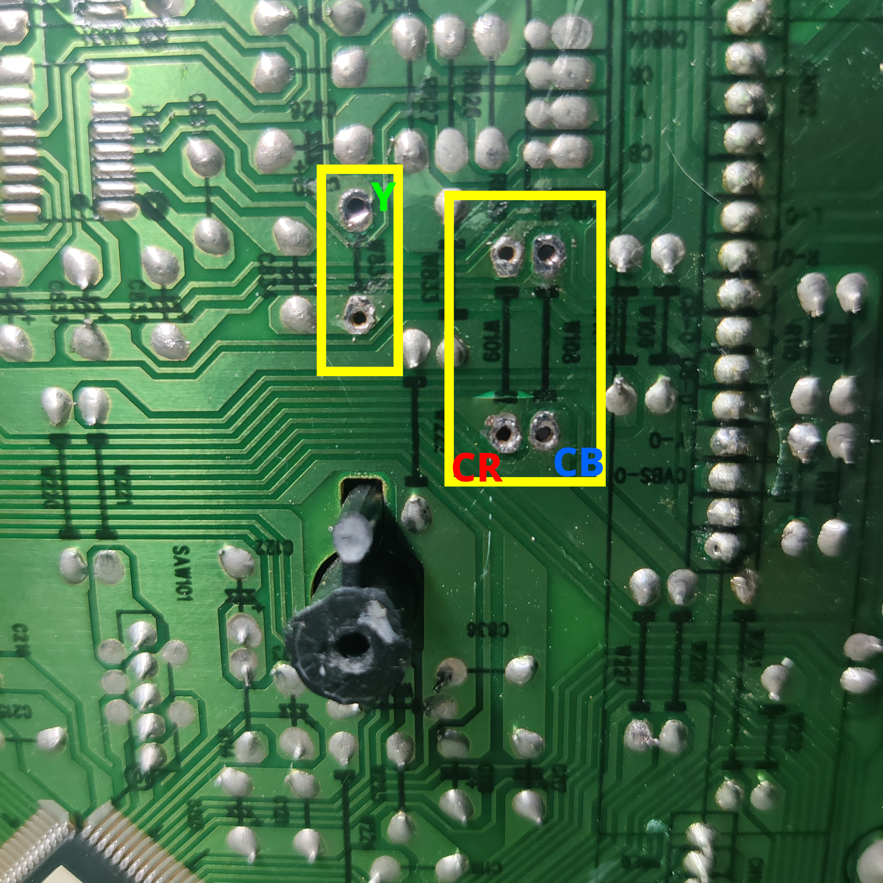
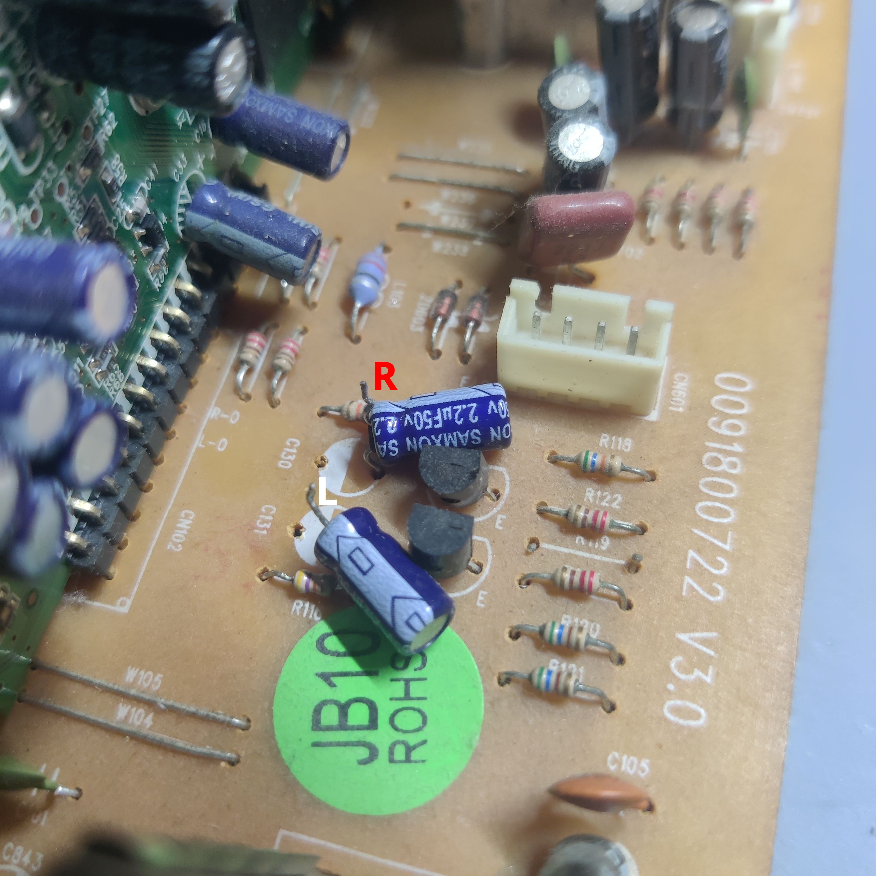
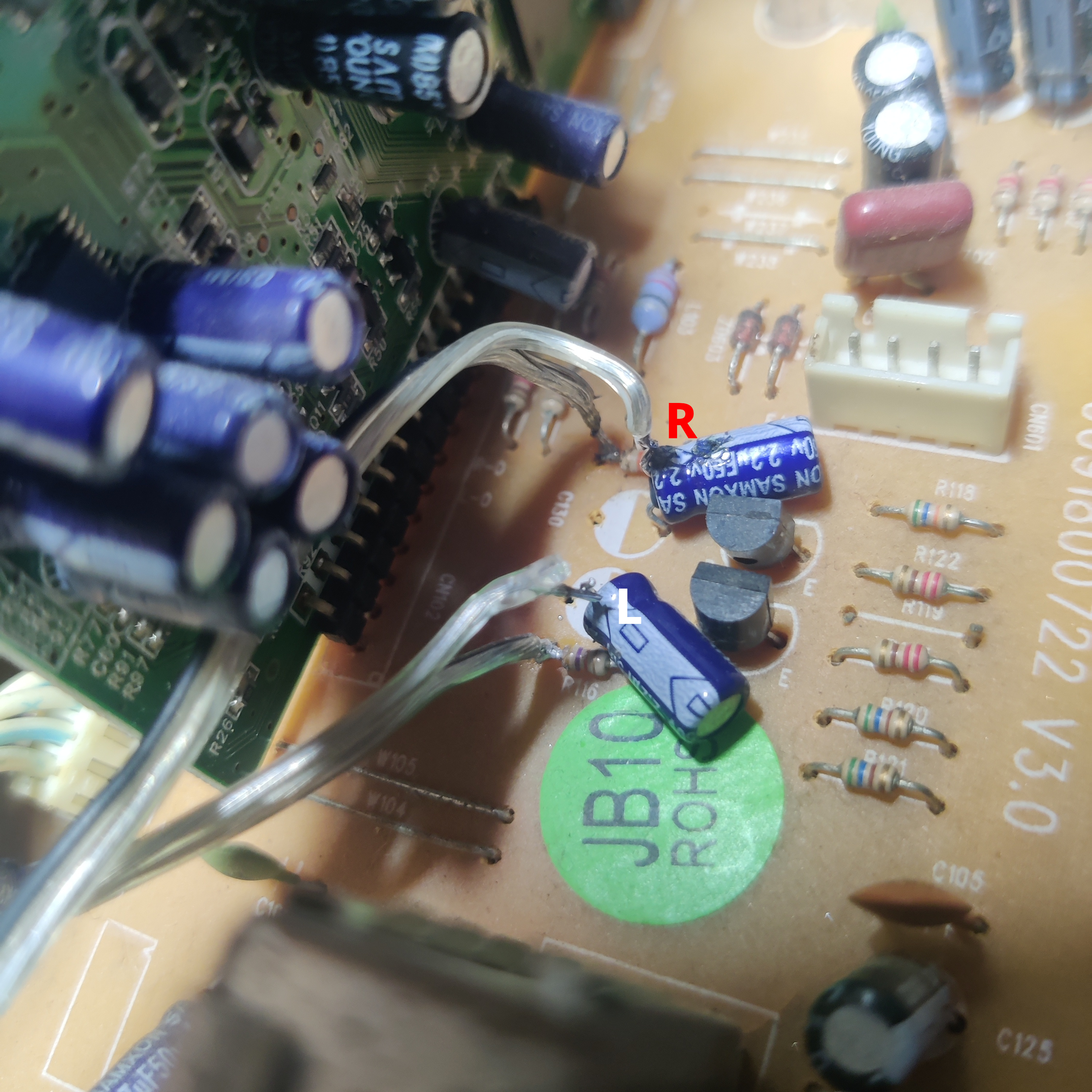
You will also need to lift the negative leads of the capacitors C131(L) and C130(R) to inject external audio to go with the video.
The audio is injected at the negative leads of these capacitors.
Step 2: Install Components and RCA Jacks
You will need to install 75 Ohm resistors for each of the Component video injection points.
The resistors will go between the injection points and ground (termination resistors).
There are ground points close to the injection points as you can see in the photo below.
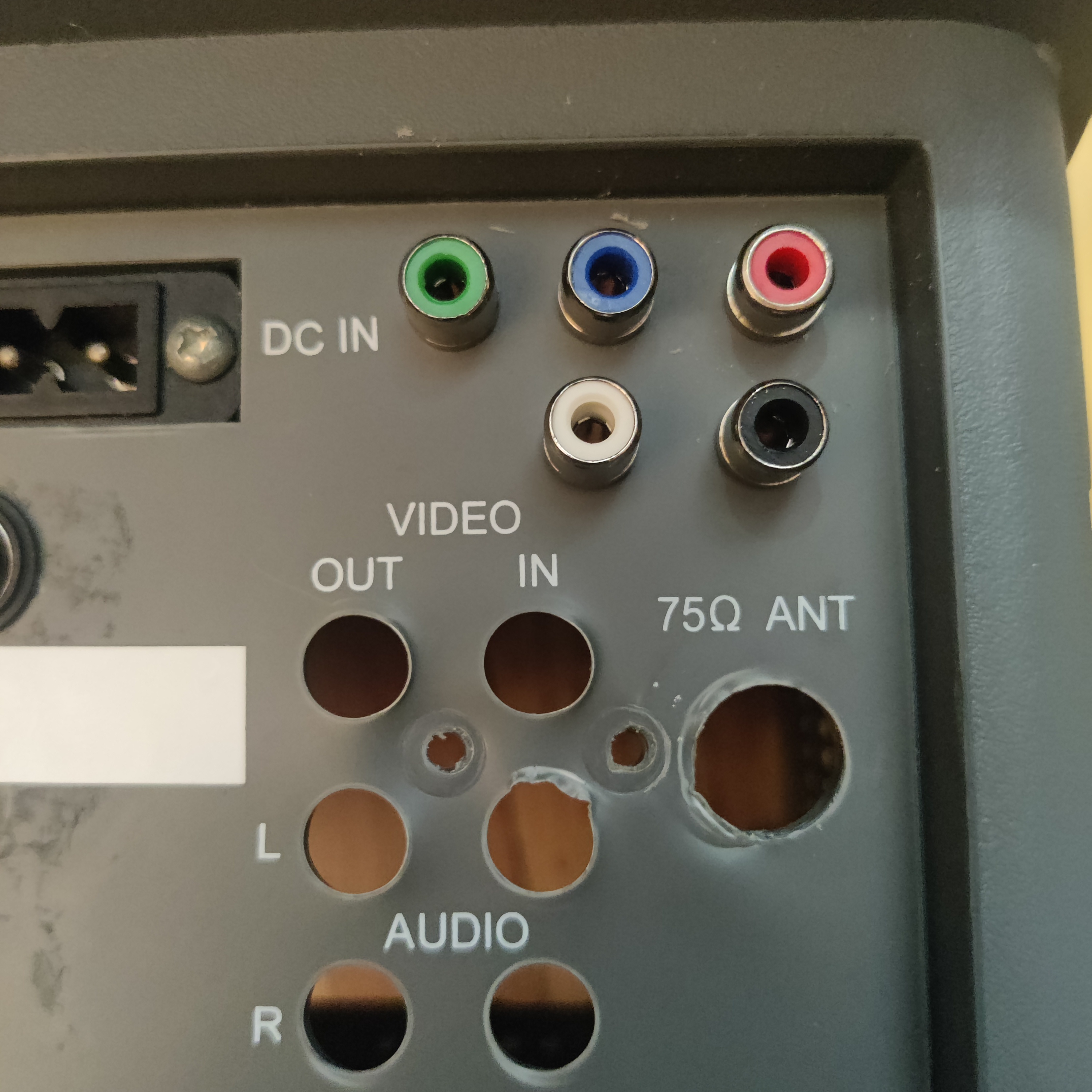
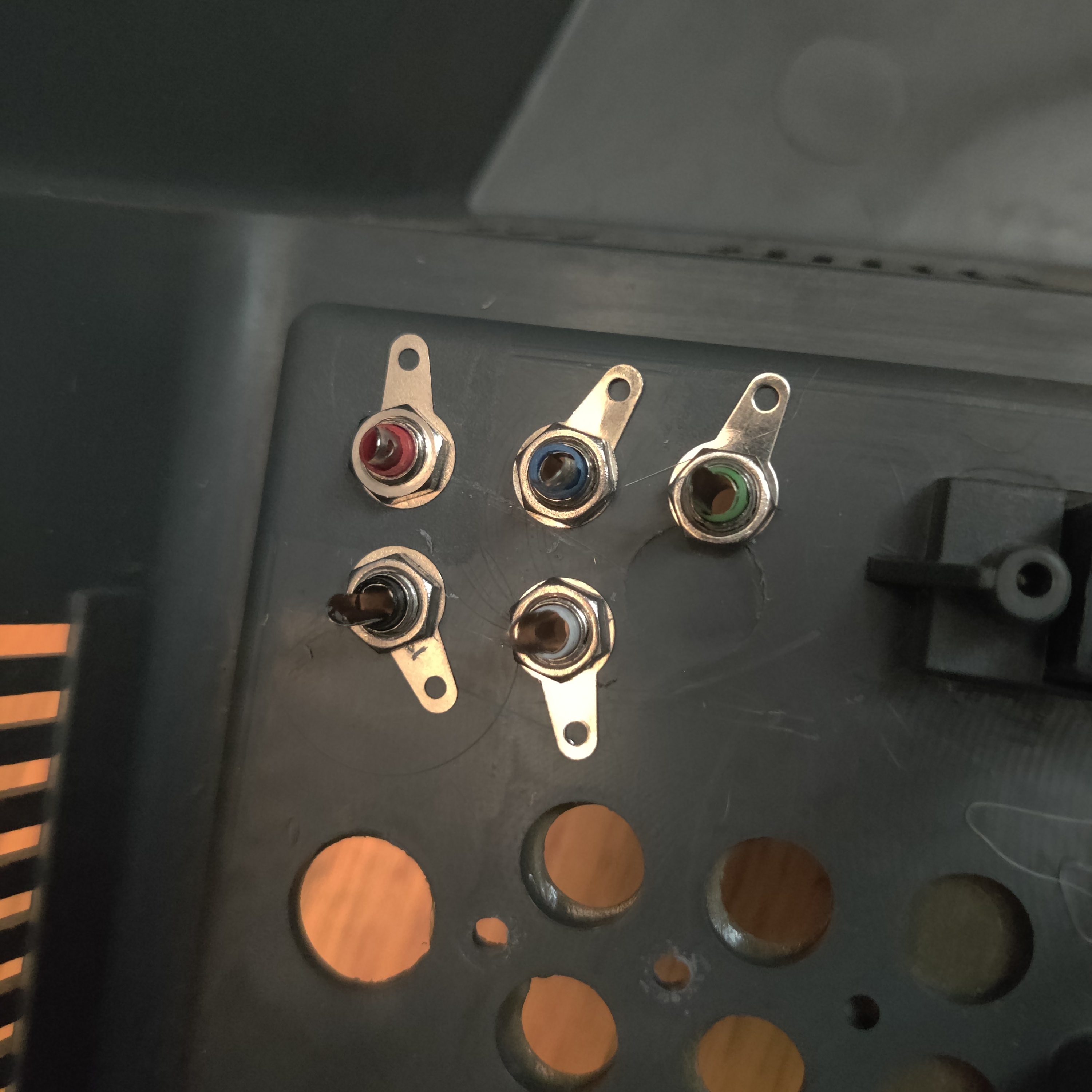
Next, install the RCA jacks on your shell however you wish. Below is an example of how they can be positioned.
You will need 5 in total, Y(green), Pb(blue) and Pr(red) for video, and L(white) and R(red) for audio.
Step 3: Run Wires
Next, run the wires from the injection points and ground points to the RCA jacks.
I like to use some kind of connector in the middle of the wire so the shell can be removed without having to cut or desolder wires.
For video you can use the injection points and ground points used in Step 2 when installing the termination resistors.
For audio, connect the Left audio input to the negative leg of C131 and the Right audio input to the negative leg of C130.
You can get ground for audio from the side of resistors R116 and R117 that is closest to the DTV board/the center of the main PCB.
Step 4: Enable Component Input in Service Menu and Adjust Levels
Finally, you will need to go into the service menu to turn on the Component video input option.
With the remote, press “MENU”, “8”, “8”, “9”, “3” in that order and you will see the service menu.
Press the MENU button until you see page 9, labelled “P9” and the options “AV2”, “YUV”, and “DVD”.
Using the Channel + and Channel - buttons, choose the “YUV” option. Then use the Volume + and Volume - buttons to set “YUV”’s value to “1”
Exit the service menu by pressing the “EXIT” button.
Switch inputs until you are on the “COMPONENT” input using the “TV/AV” button on the remote.
Plug in a Component video device to your new RCA jacks.
You should see a picture on the screen. If you do not, check your wiring and cables.
You’ll notice that the picture is shifted to the side. The horisontal position needs to be adjusted, which is called “H PHASE” in the service menu.
Doing so will adjust it for all inputs, so in order to find the balance that has all inputs centered you will need to adjust “Y DLY” as well as “H PHASE”.
“Y DLY” will shift the horizontal position for all inputs other than Component, and “H PHASE” will adjust the horizontal position for all inputs. So you need to adjust “Y DLY” until Composite video’s position matches Component’s position, then adjsut “H PHASE” to center all the inputs.
“H PHASE” is on “P1” of the service menu and “Y DLY” is on “P10”
Additionally, the picture level of Component will be lower than the other inputs, so that needs to be adjusted in the service menu.
You will want to turn on “CRCB GAIN UP” by setting it to “1” and then increase “RB YUV”, “GB YUV” and “BB YUV” by some amount (likely between 1 and 16) to get a similar picture level on Component as you do with other inputs. These adjustments are on “P3” of the service menu.
That’s it, you should now be able to enjoy Component Video on your set!
NOTE: Because this mod disconnects the TV Tuner’s output and uses that location to inject the signals, you will see the Component input on the “TV” input, but it will not have audio. You must use the “COMPONENT” input to have audio.
You can view the Service Manual with schematics for more info. The model doesn’t match up but this is in fact the same TV PCB and schematic.
This service manual has details on the service menu options and how to use it, but the schematics in it are unreadable.
This article is also hosted on Sunthar.com
Back to top