Sony KV-20S11 - RGB SCART Mod
This guide will cover how to RGB SCART mod the Sony KV-20S11.
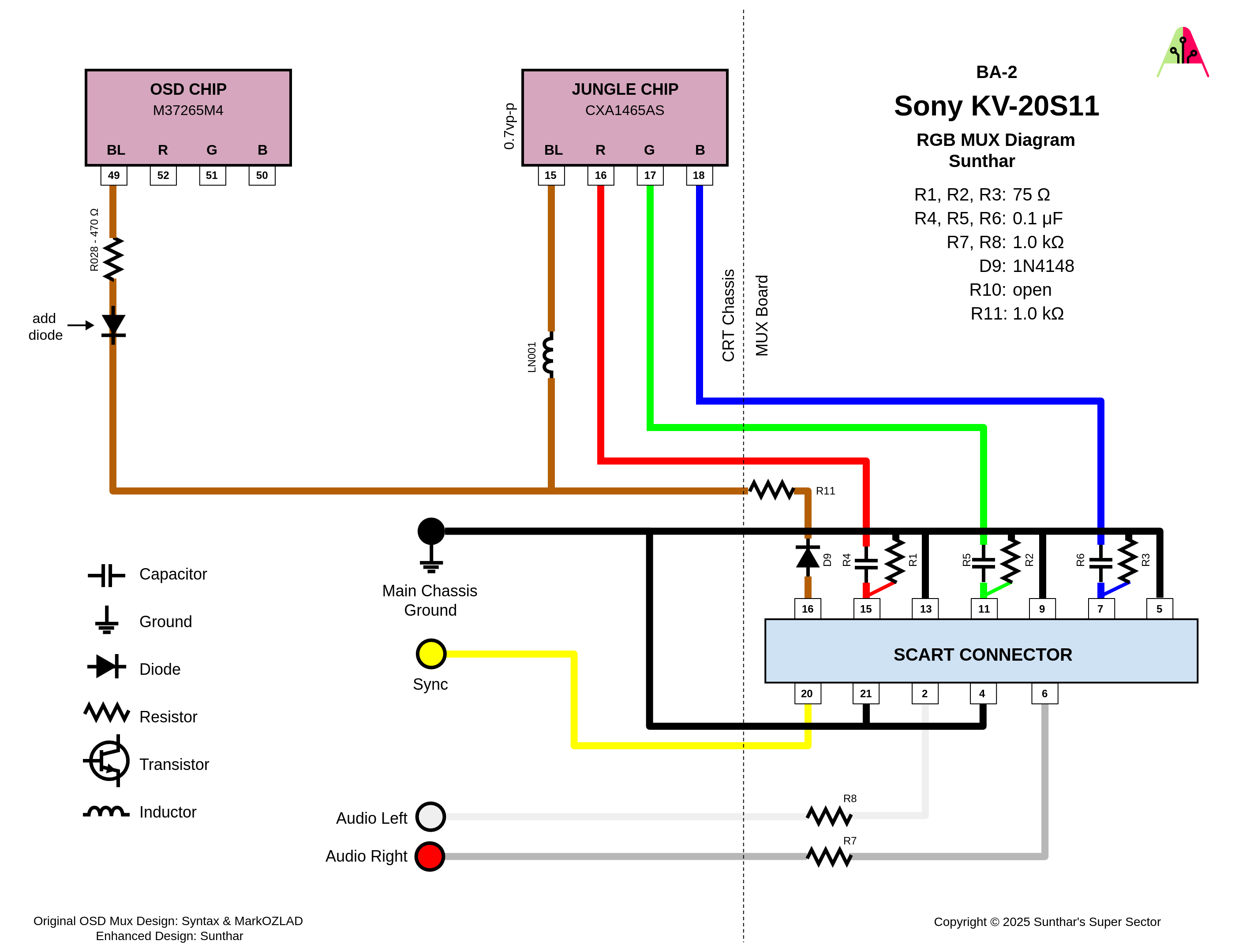
This is one of the easier CRTs to RGB mod as the jungle chip has an extra set of RGB inputs. I installed the RGB mod using Sunthar’s RGB MUX diagram and guide for the BA-2 Chassis here.
Step 1: Remove Components and Cut Traces
Open up your CRT and pull out the large PCB in the bottom center of the TV. There is a plastic snapping bit on the left side of the board that keeps it in place. You’ll need to bend it back to let the PCB slide out the case.
On the bottom of the board, locate R325 near IC301 pin 15 and remove it. You’re also going to need to cut the traces that connect together pins 15, 126 and 17 of IC301. The easiest way to do this is to make cuts between pin 15 and 16, and between pin 16 and 17, as the traces run directly between the pins. The guide on Sunthar’s page for the BA-2 has a picture that shows this.
Step 2: Connect Wires to go to SCART Port
RGB wires will be soldered directly to pins 15, 16 and 17 of IC301. Red can also be soldered to the pad left over by removing R325. See the image below.
Sync is soldered directly to the composite input pin, and audio L and R are soldered to the audio input pins on the bottom of the PCB. These are the large pins below the input jacks that are not the ones closest to the PCB edge. The ones close to the edge are Ground and is where the ground wire(s) going to the MUX can be soldered to. See the photo below.
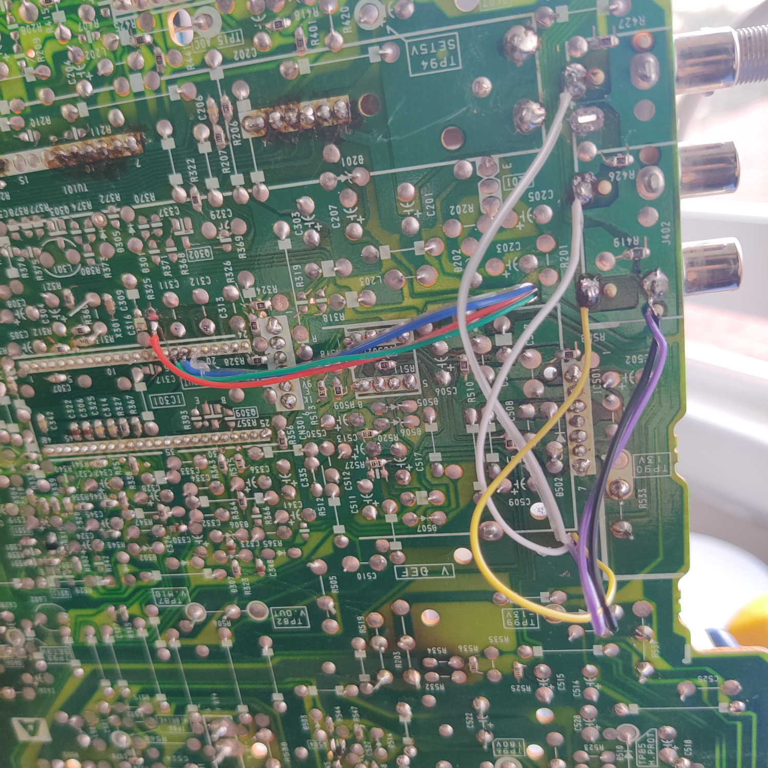
I routed these wires through holes in the PCB. You can see their locations in the photos.
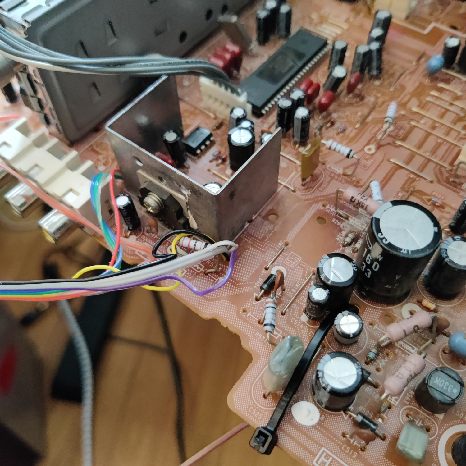
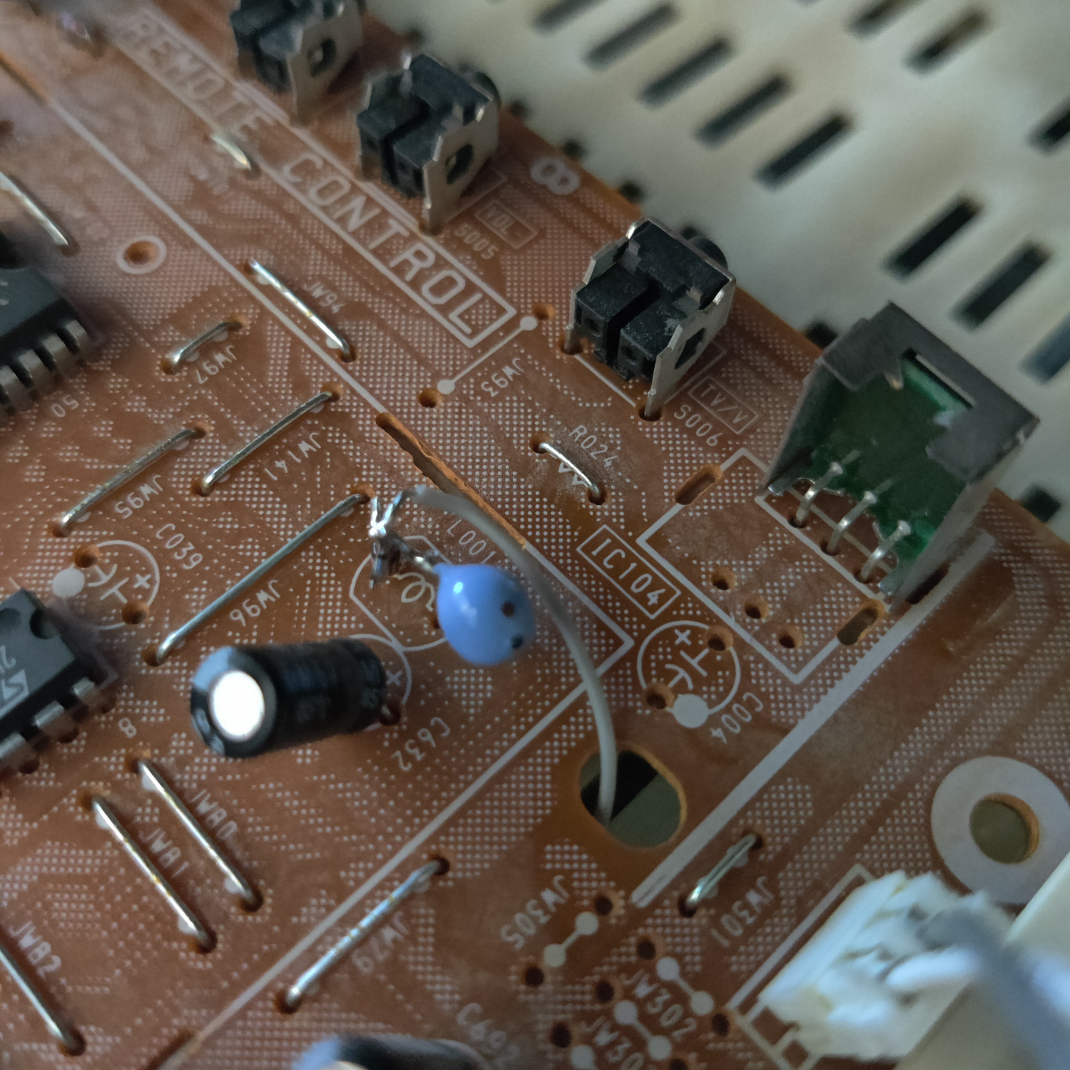
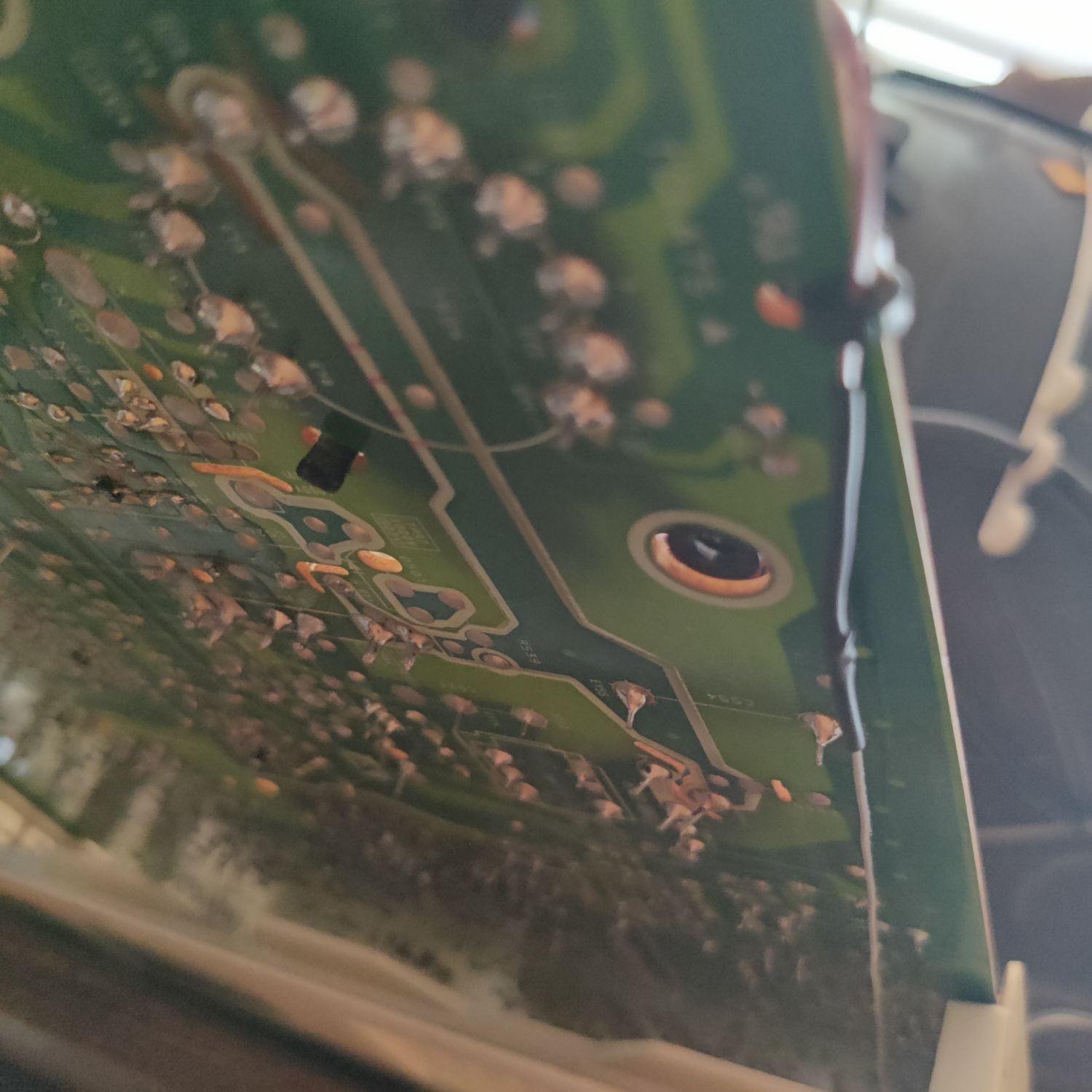
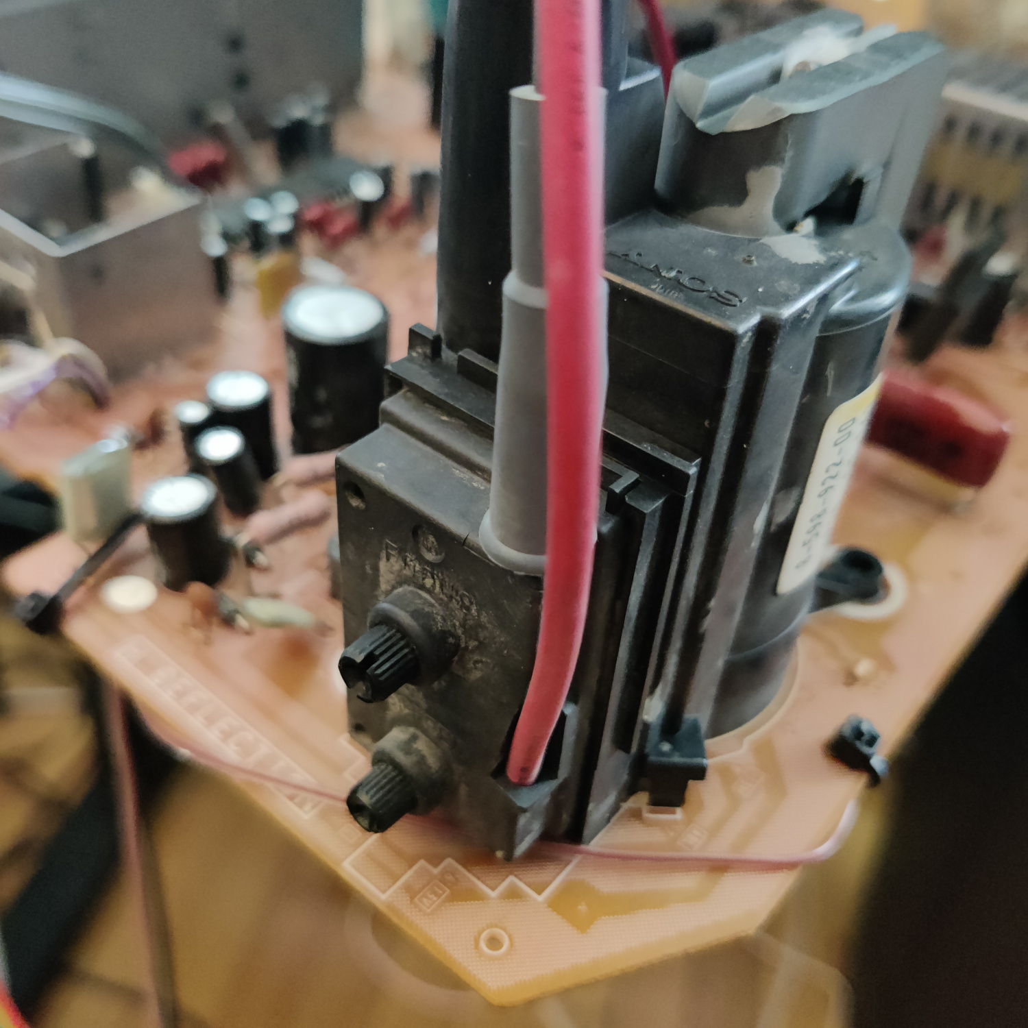
The Blanking wire solders to the cathode side of a diode that is inserted in the left hole of L001. You will need to lift that side of L001 and insert and solder the anode side of the diode in the hole where the lifted inductor leg was, then solder the lifted inductor leg to the cathode side of the diode. The blanking wire is soldered to the cathode side of the diode, same as the lifted inductor leg. See photo below.
It’s necessary to route this wire under the PCB or you will see a lot of video noise. I routed it through the hole next to the inductor and under the PCB to the corner where the Flyback transformer is and zip tied it to follow the pcb edge. See the photos below.
That’s all the wires you’ll need to connect to your SCART port.
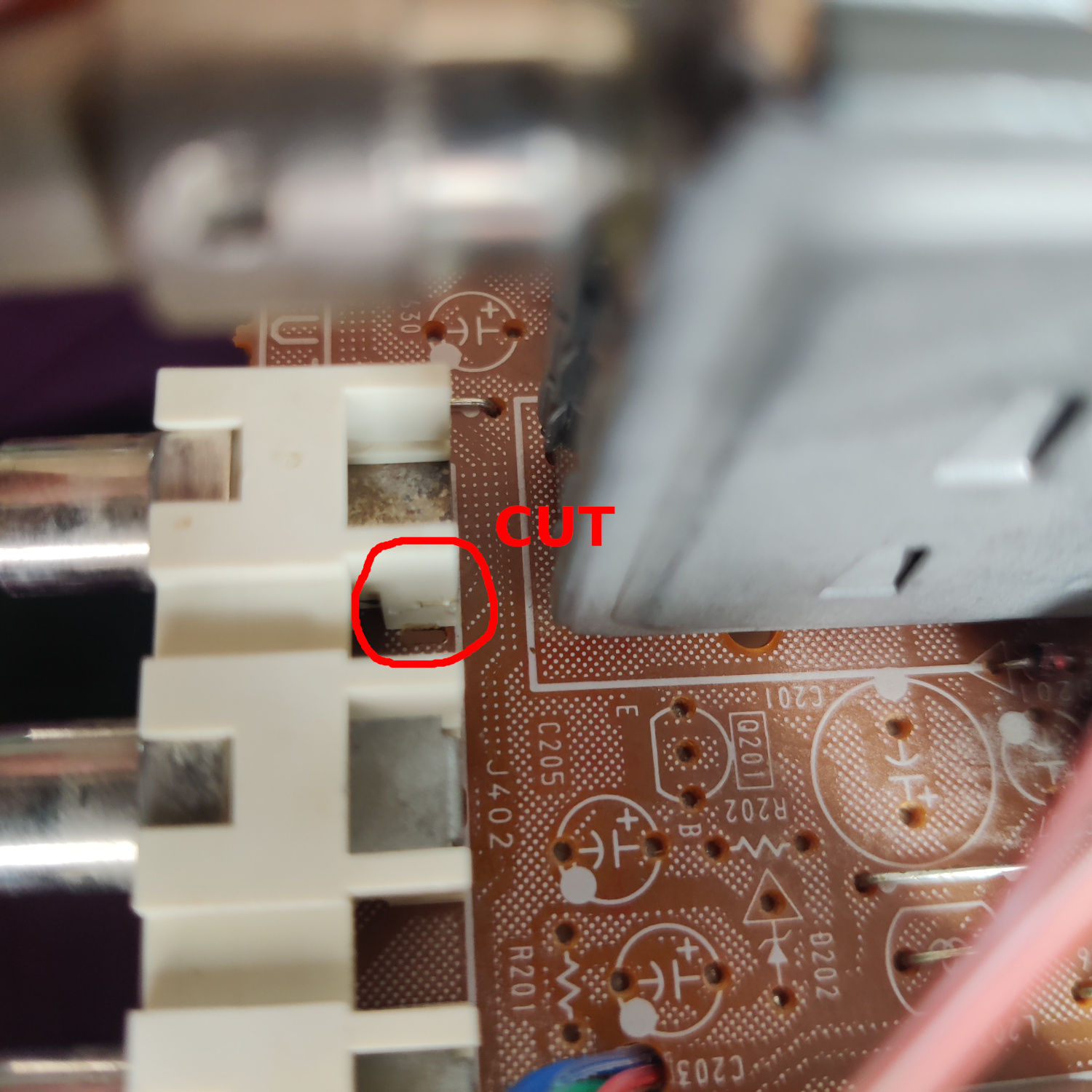
In order for stereo audio to work without having an RCA cable plugged into the right/red audio input, you’ll need to cut the pin on the side of the right audio jack. This pin detects if there is a cable plugged into right audio, and if there is not it routes left audio into right audio, effectively making the audio input mono. This has to be cut so that left audio does not get routed to right audio when there is no cable plugged into the RCA jacks. See photo below for what to cut.
Step 3: Prepare your SCART Port
If you purchased a SCART port from Sunthar, you can follow the instructions on his site for this section.
CRT Database also has a great guide on creating a clean SCART connector setup, so check that out as well for more info.
If you want to make your own, you can use this SCART female socket from AliExpress, which you can find elsewhere. The Ali listing calls it a 21 PINS CS Type Scart Female Socket Connector Jack Female PCB Mount 21 PIN SCART
Then you can use some prototyping board or solderable breadboard to hold the components. You can also do this without a board, you’ll just need to make sure to connect your components with enough support that they won’t break off during use/install/movement.
TLDR info for making your own is:
- RGB inputs are 75 Ohm terminated then connect to your RGB wires from earlier with 100nF capacitors.
- The Blanking input is connected to a 1N4148 diode, then a 1K Ohm resistor to the blanking wire from earlier.
- Sync input is connected directly to the sync wire soldered earlier.
- Audio left and right are connected to the audio wires soldered earlier with 1K Ohm resistors inline.
- Ground is connected to the ground wires soldered earlier.
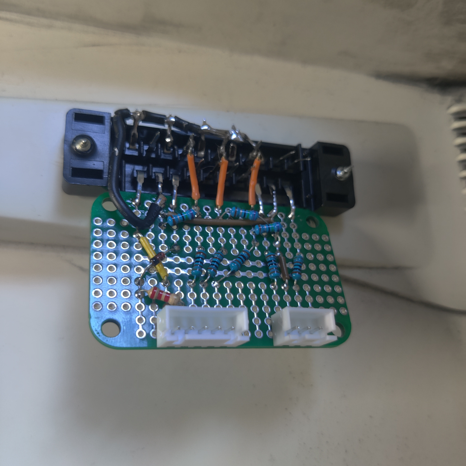
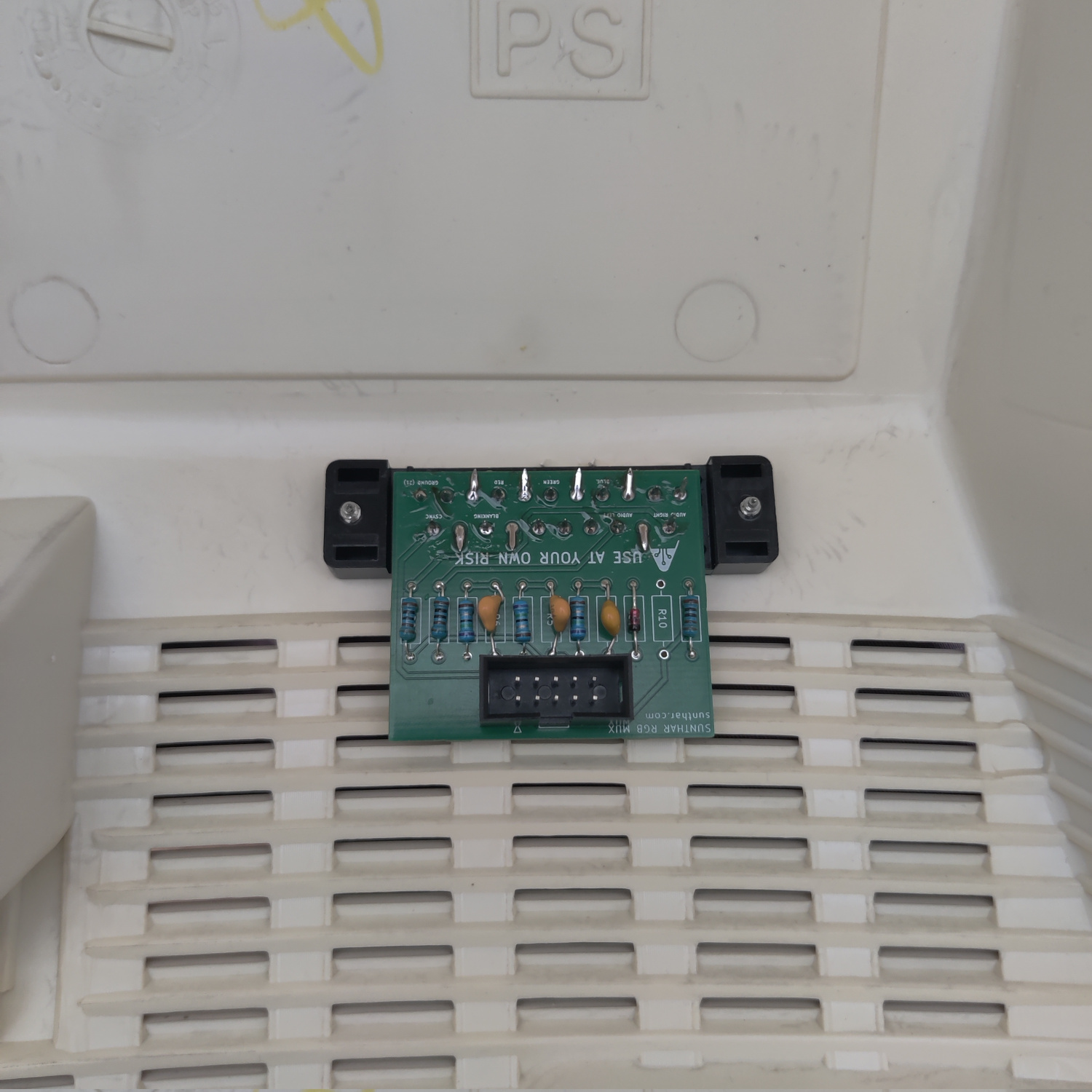
You can see an example “homemade” SCART mux below.
That’s all for the wiring, you should now test your work to ensure that it is all functioning properly.
Step 4: Mounting the SCART port
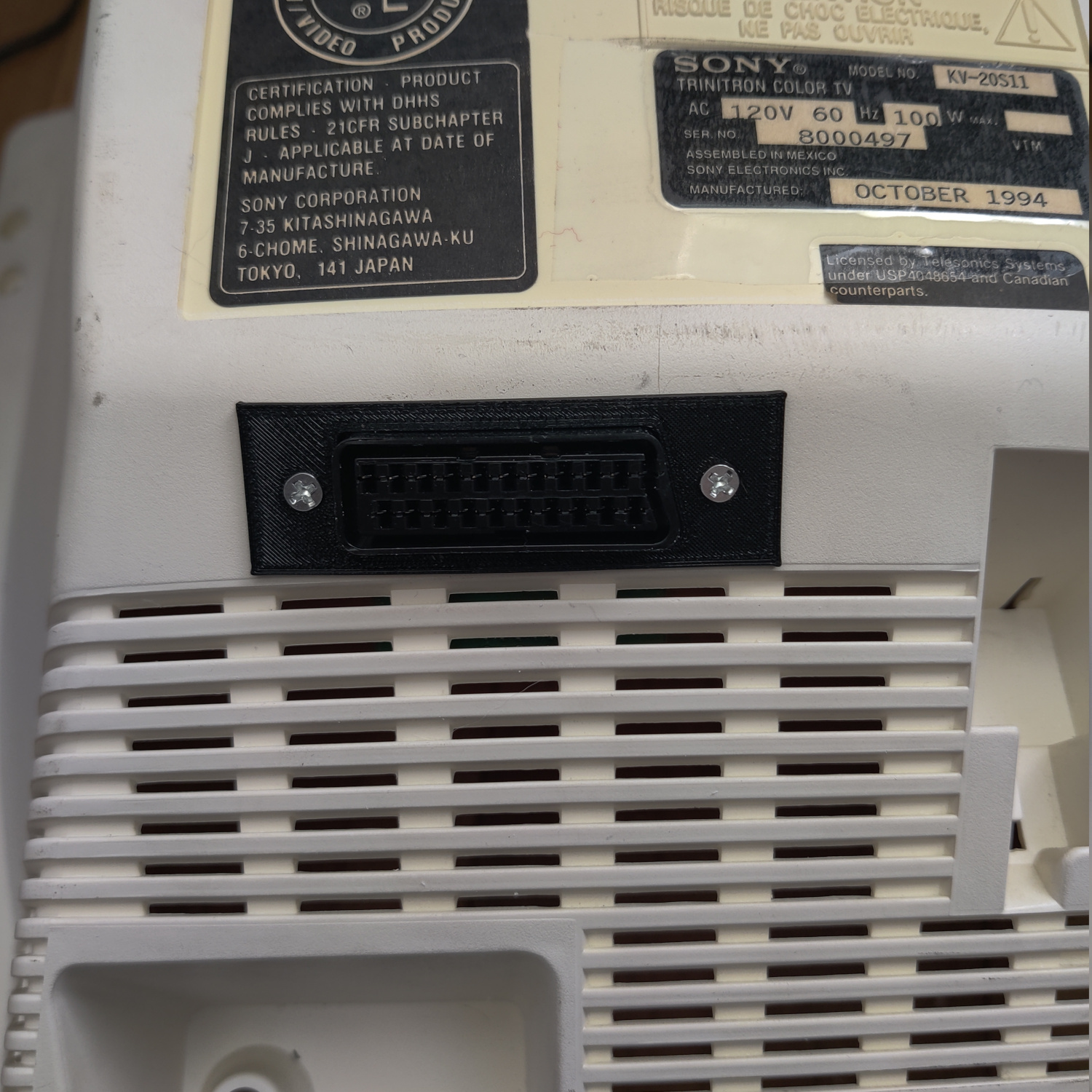
I used a 3D-printed SCART port panel to cover up any not-so-perfect cutting I did for the port.
To do the actual cutting I drew an outline of the port using the 3D-printed part and then used a sharp razor blade box cutter to cut the outline out. Then I drilled holes to screw into the port using some screws I have that are the right size to thread into the plastic of the SCART port. You can see the final results below.
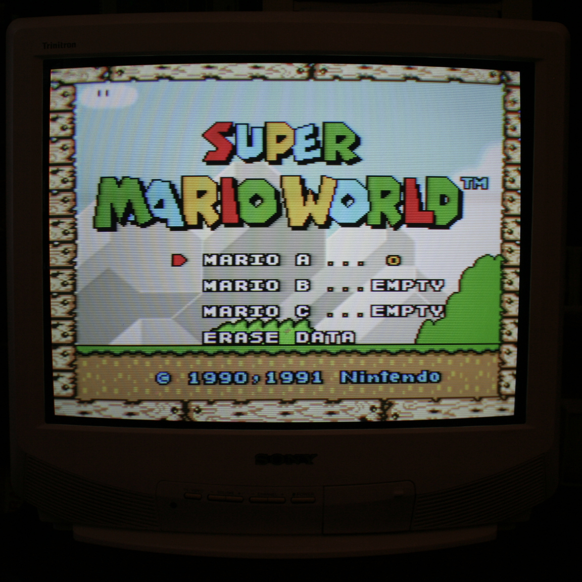
And that’s it for the mod! The picture will appear on the Video input when you plug in a console and turn it on.
This article is also hosted on Sunthar.com
Back to top