JVC C-13111 - RGB SCART Mod
This guide will cover how to RGB SCART mod the JVC C-13111. It will be necessary to remove or at least pull out the main board to do this mod.
Step 1: Remove/Replace components
Open up your CRT and pull out the large PCB in the bottom center of the TV. There are some clips at the front where the buttons are, it is easiest to remove the board if it is at an upward angle as this disengages those clips more.
On the bottom of this board, locate R738, R740, R742 and remove them. They are located near IC701 which is at the front of the TV. The service manual, available on Sunthar’s page for the C-13310 has a picture that shows the location of them.
Step 2: Connect Wires to go to SCART Port
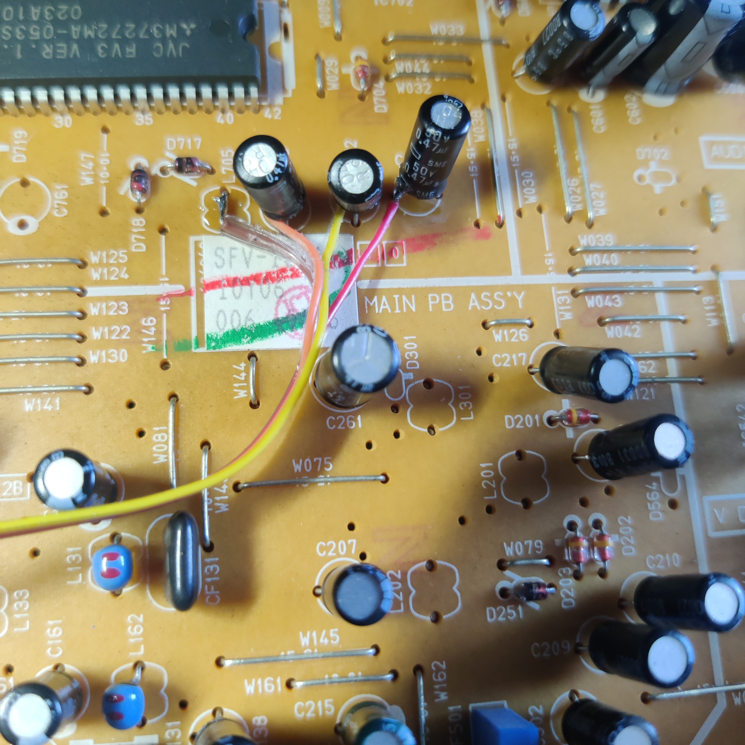
RGB wires will be soldered to the side of C801, C802 and C803 that is not connected to IC201. See the image below, R goes to C801 left side, G goes to C802 top side, and B goes to C803 top side when viewing the PCB such that the majority of the component labels are facing you.
The Blanking wire solders to the wire bridge that is installed where L705 would go. See photo below.
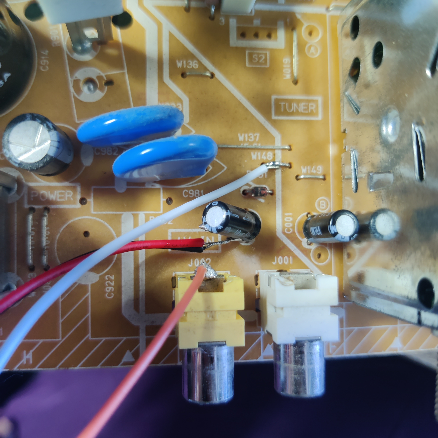
Connect Sync to the center pin of the yellow composite input in the back.
Connect the Left and Right audio wires both to the negative (-) side of C651, near the audio input in the back.
Connect the ground wire(s) from the mux board to any suitable ground point on the board (I used jumper W148 near the audio and video inputs in the back).
See the photo below for the wiring of these connections.
That’s all the wires you’ll need to connect to your SCART port.
Step 3: Prepare your SCART Port
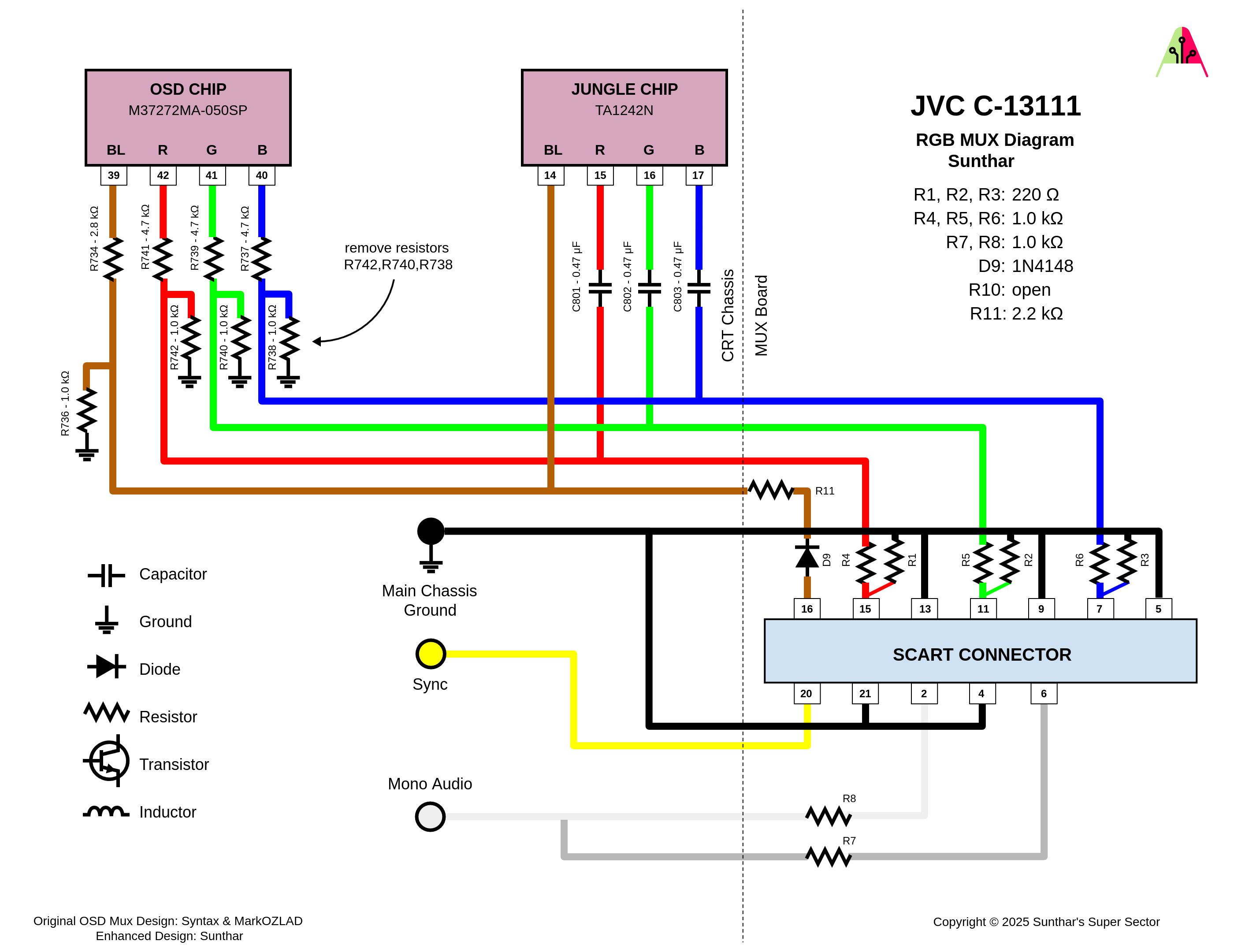
Use the following MUX diagram to create your RGB SCART MUX. DO NOT USE THE ONE FOR THE C-13110 ON SUNTHAR’S SITE! It does not have the correct values to get the best signal for this set. Specifically, you need to terminate the RGB lines with 220 ohms instead of 75 ohms to get the best signal. Sunthar has noted that this jungle chip works better with 220 Ohm termination resistors for other sets that use this same jungle chip here.
If you purchased a SCART port from Sunthar, you can follow the instructions on his site for this section. IMPORTANT NOTE: The MUX diagram for the C-13110 is not correct for the C-13111, use the one shown above for the correct resistor values.
CRT Database also has a great guide on creating a clean SCART connector setup, so check that out as well for more info.
If you want to make your own, you can use this SCART female socket from AliExpress, which you can find elsewhere. The Ali listing calls it a 21 PINS CS Type Scart Female Socket Connector Jack Female PCB Mount 21 PIN SCART
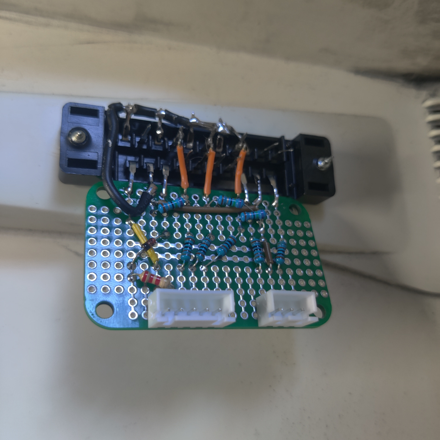
Then you can use some prototyping board or solderable breadboard to hold the components. You can also do this without a board, you’ll just need to make sure to connect your components with enough support that they won’t break off during use/install/movement.
TLDR info for making your own is:
- RGB inputs are 220 Ohm terminated then connect to your RGB wires from earlier with 1K Ohm resistors.
- The Blanking input is connected to a 1N4148 diode, then a 2.2K Ohm resistor to the blanking wire from earlier.
- Sync input is connected directly to the sync wire soldered earlier.
- Audio left and right are connected to the audio wires soldered earlier with 1K Ohm resistors inline.
- Ground is connected to the ground wires soldered earlier.
You can see an example “homemade” SCART mux below.
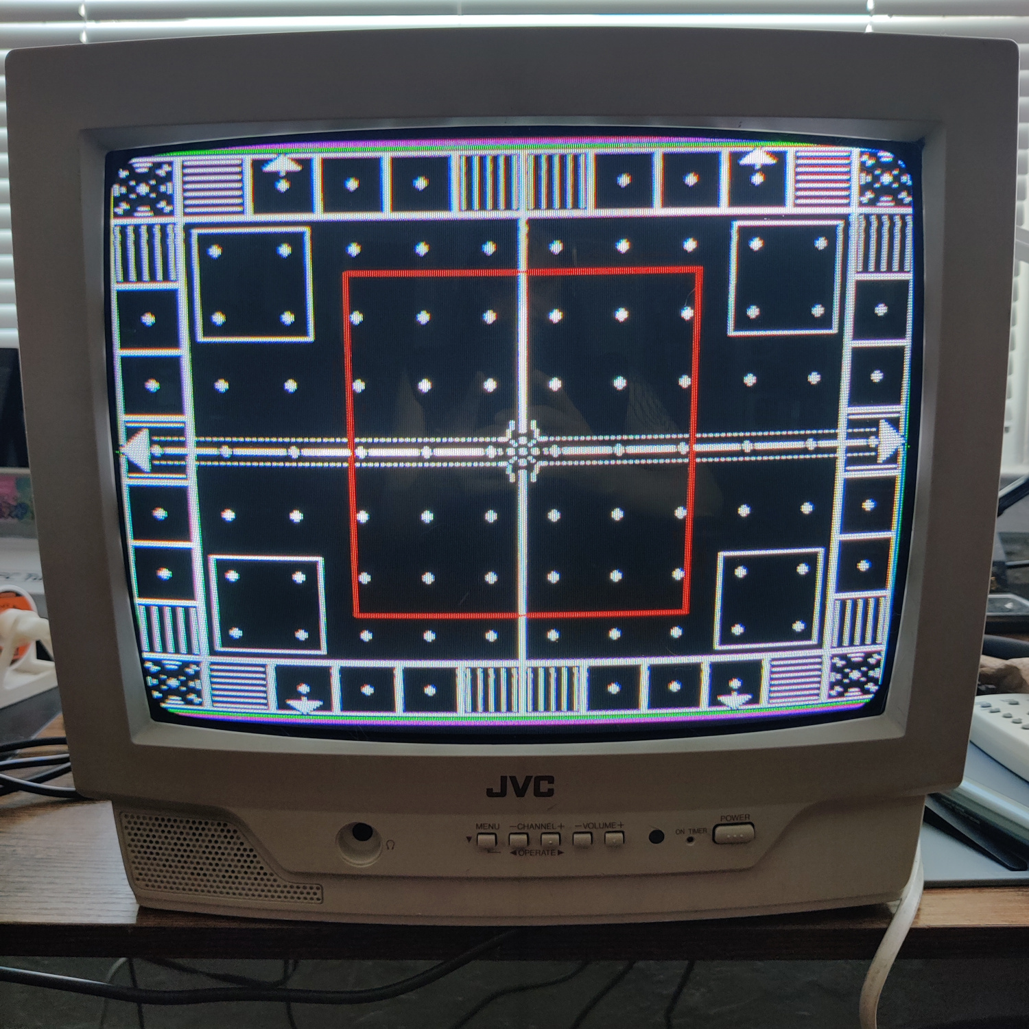
That’s all for the wiring, you should now test your work to ensure that it is all functioning properly.
Step 4: Mounting the SCART port
I used a 3D-printed SCART port panel to cover up any not-so-perfect cutting I did for the port.
To do the actual cutting I drew an outline of the port using the 3D-printed part and then used a sharp razor blade box cutter to cut the outline out. Then I drilled holes to screw into the port using some screws I found that were the right size to thread into the plastic of the SCART port. You can see the final results below.
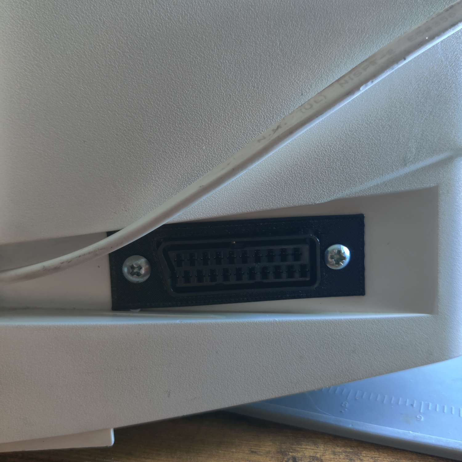
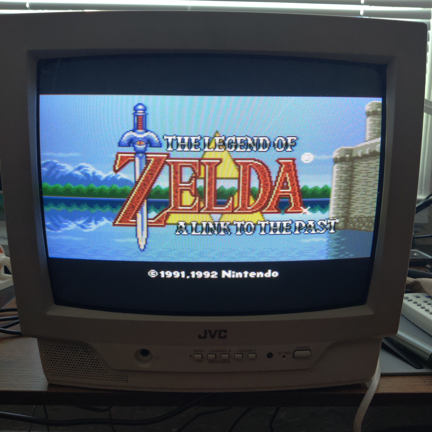
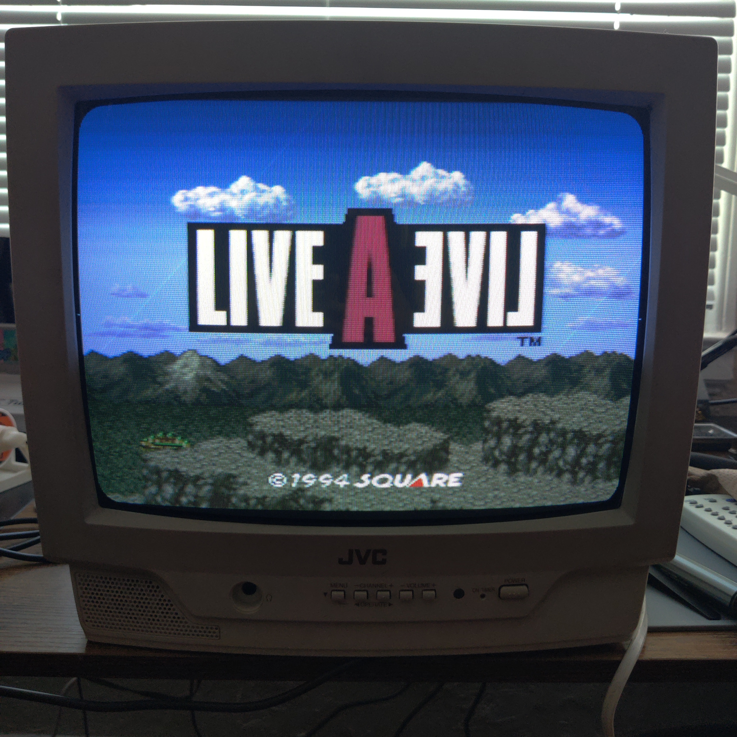
And that’s it for the mod! The picture will appear on the Video input when you plug in a console and turn it on.
This article is also hosted on Sunthar.com
Back to top