Sony KV-13FM12 - RGB SCART Mod
This guide will cover how to RGB SCART mod the Sony KV-13FM12. RGB Modding this CRT is pretty straightforward as all the solder points are accessible without removing the main A board.
I installed the RGB mod using Sunthar’s RGB MUX diagram here, and Davide Bacchet’s guide here. Though the way I installed the mod is slightly different than these guides.
Step 1: Remove/Replace components
Open up your CRT and pull out the vertical PCB on the left side of the TV. It is connected to the main board via two connectors that you will have to unlatch to get the board loose.
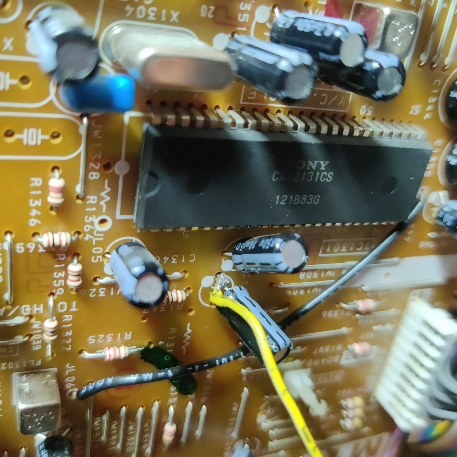
On the bottom of this board, locate R1084, R1085, R1086 and remove them.
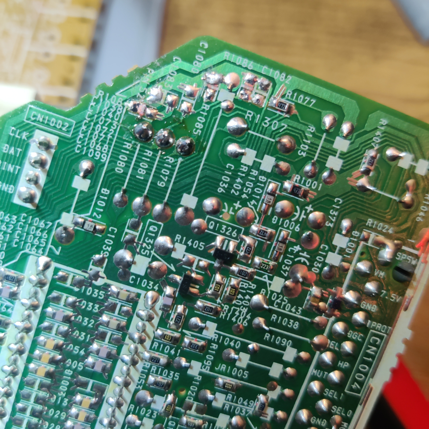
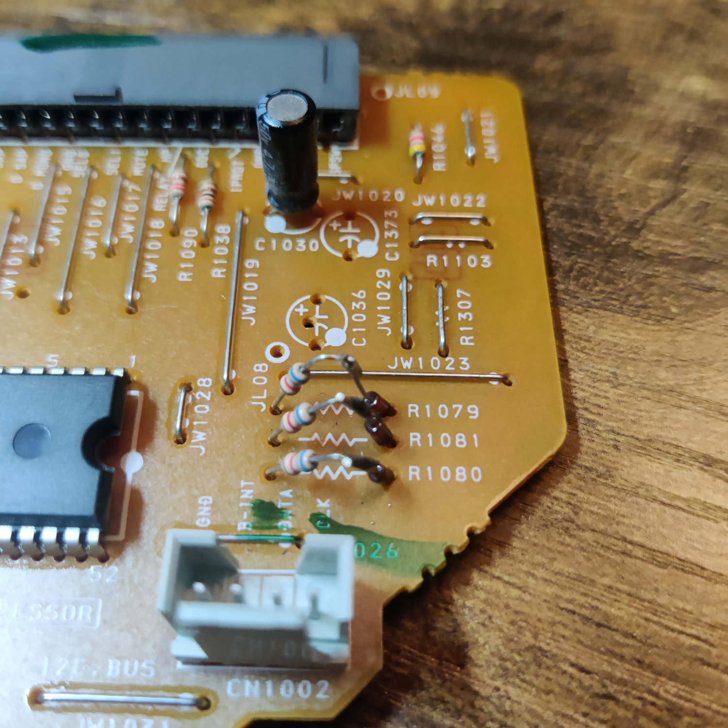
Then locate the resistors R1079, R1080 and R1081. Lift the side of these resistors that is closest to the edge of the PCB and insert 1N4148 diodes into the holes the resistors were lifted from.
Be sure to insert the cathode (-) side of the diodes into the holes and solder them in place. Then, solder the other sides of the diodes to the lifted resistor legs.
Step 2: Connect Wires to go to SCART Port
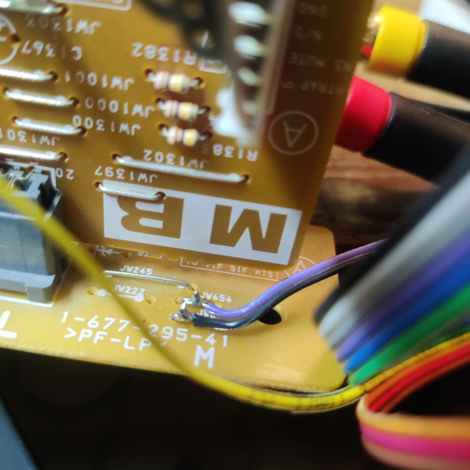
RGB and Blanking wires will be soldered to jumpers JW1337, JW1336, JW1335, and JW1334, respectively. See the image below for their location.
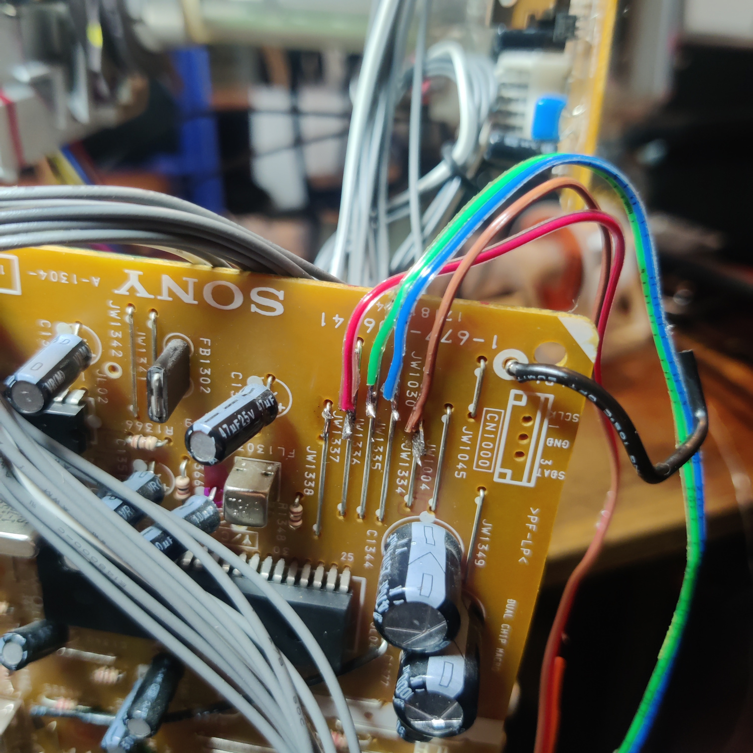
Connect Sync to the negative (-) side of the capacitor C1385 near the jungle chip. Connecting it here will prevent the picture from shifting like it would if Sync were going through the Comb filter by being connected to the composite input.
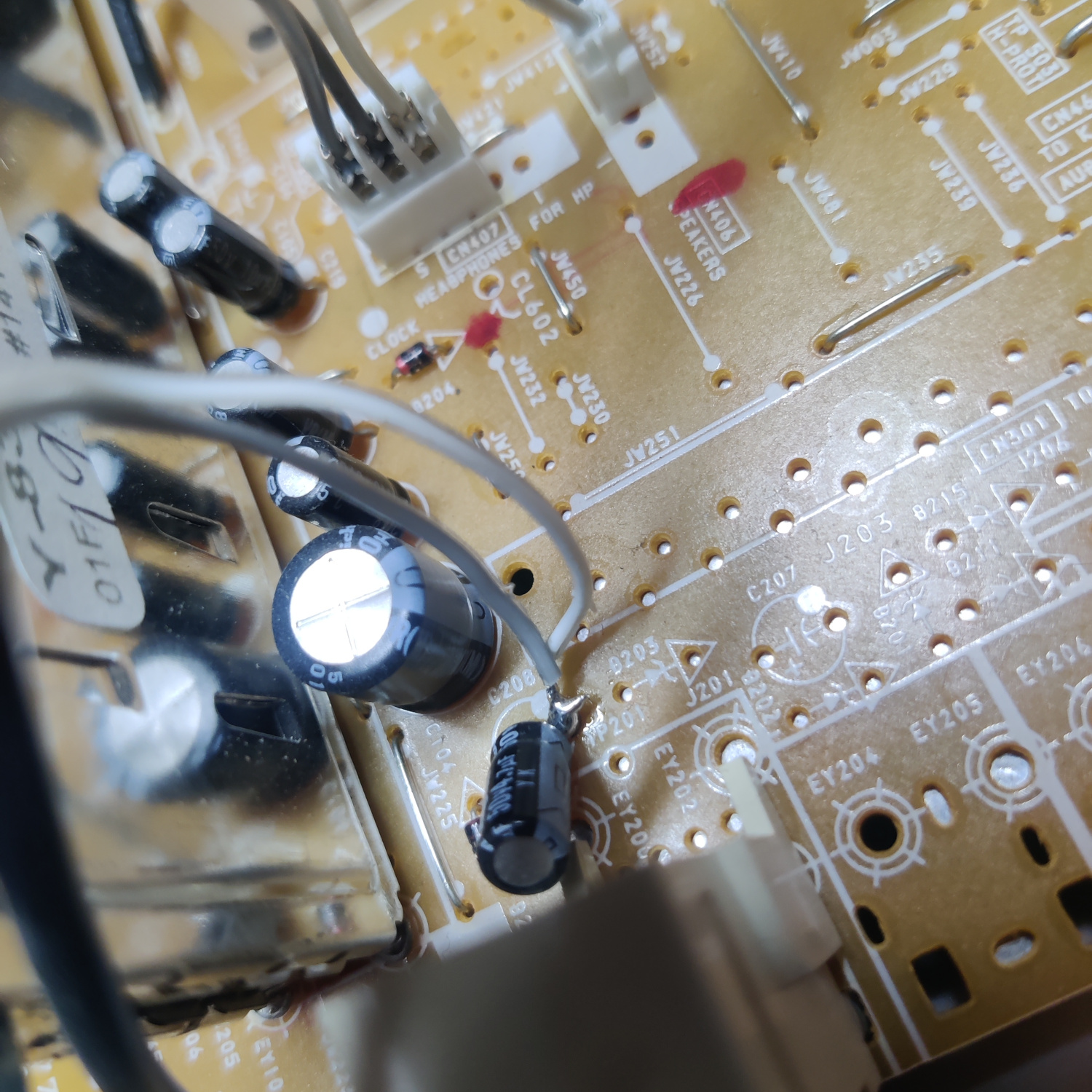
Connect the Left and Right audio wires to the negative (-) side of C208 on the main A board.
Connect the ground wire(s) from the mux board to jumper JW654 or the jumper right below it (or any suitable ground point).
That’s all the wires you’ll need to connect to your SCART port.
Step 3: Prepare your SCART Port
If you purchased a SCART port from Sunthar, you can follow the instructions on his site for this section.
CRT Database also has a great guide on creating a clean SCART connector setup, so check that out as well for more info.
If you want to make your own, you can use this SCART female socket from AliExpress, which you can find elsewhere. The Ali listing calls it a 21 PINS CS Type Scart Female Socket Connector Jack Female PCB Mount 21 PIN SCART
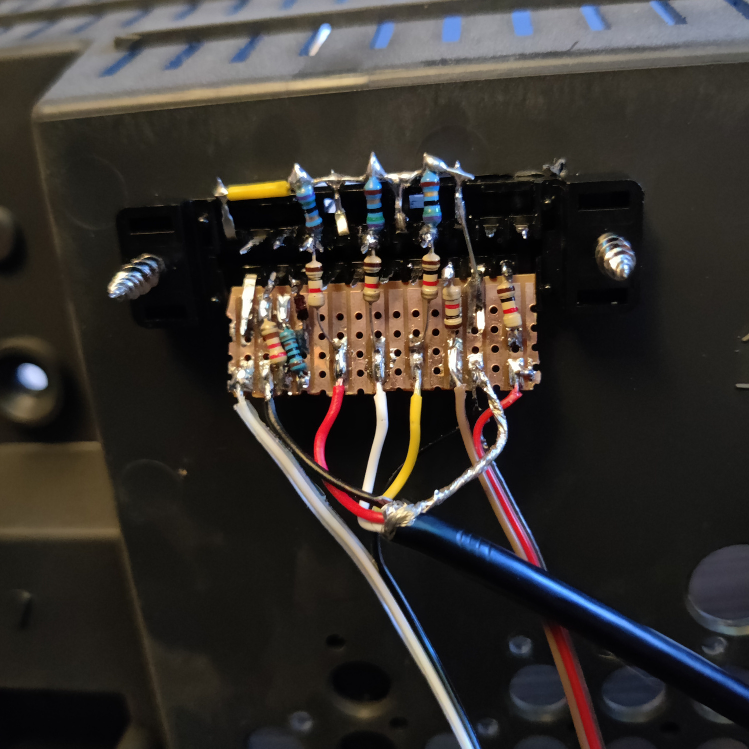
Then you can use some prototyping board or solderable breadboard to hold the components. You can also do this without a board, you’ll just need to make sure to connect your components with enough support that they won’t break off during use/install/movement.
Use the following diagram from Sunthar’s page on this set to create your RGB SCART MUX.
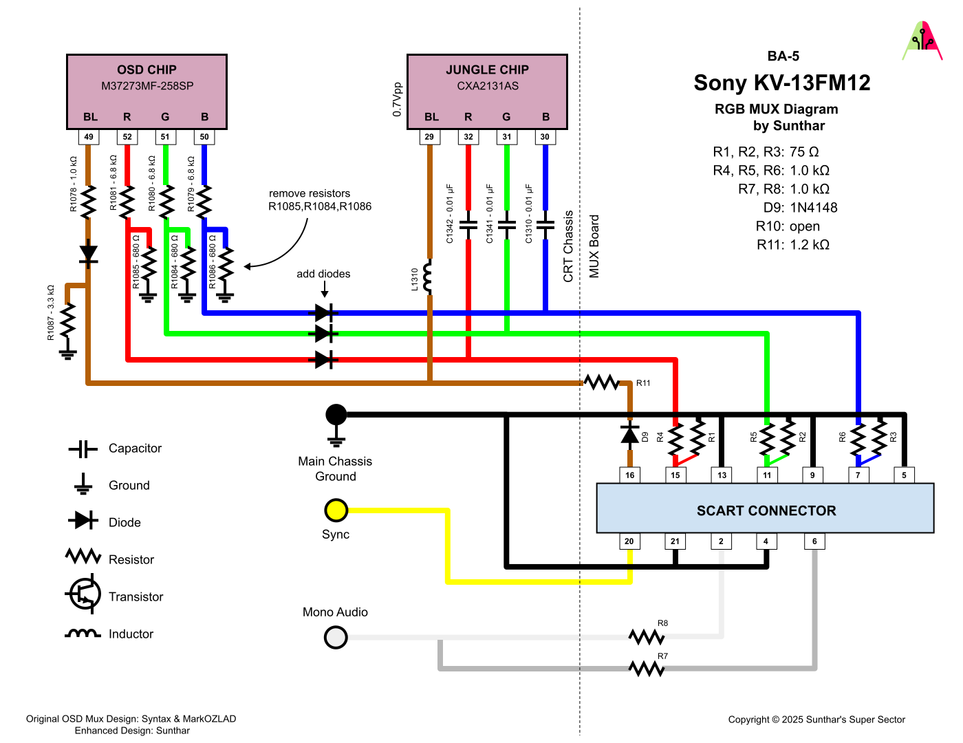
TLDR info for making your own is:
- RGB inputs are 75 Ohm terminated then connect to your RGB wires from earlier with 1K Ohm resistors.
- The Blanking input is connected to a 1N4148 diode, then a 1.0K-1.2K Ohm resistor to the blanking wire from earlier.
- Sync input is connected directly to the sync wire soldered earlier.
- Audio left and right are connected to the audio wires soldered earlier with 1K Ohm resistors inline.
- Ground is connected to the ground wires soldered earlier.
You can see an example “homemade” scart mux below.
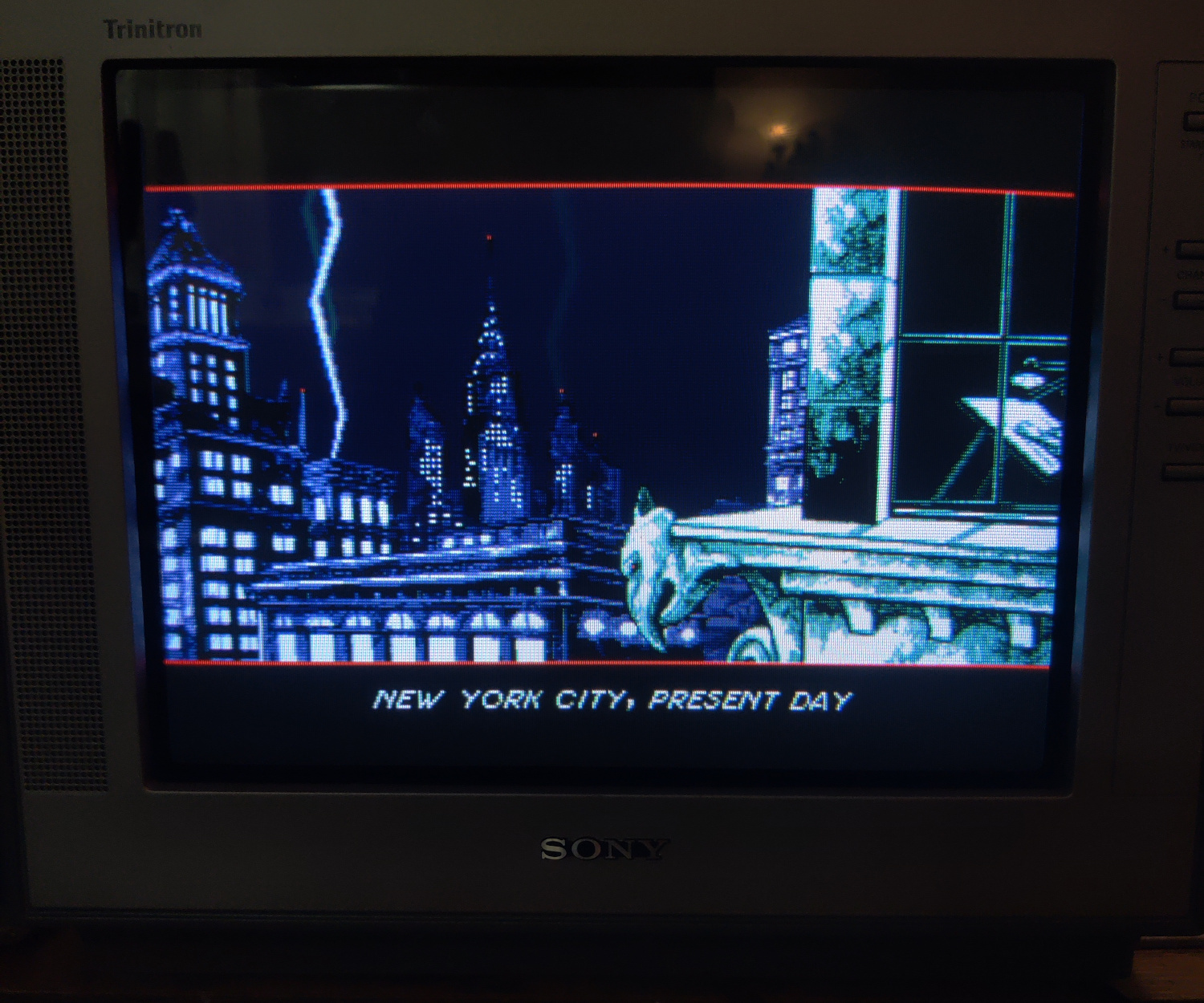
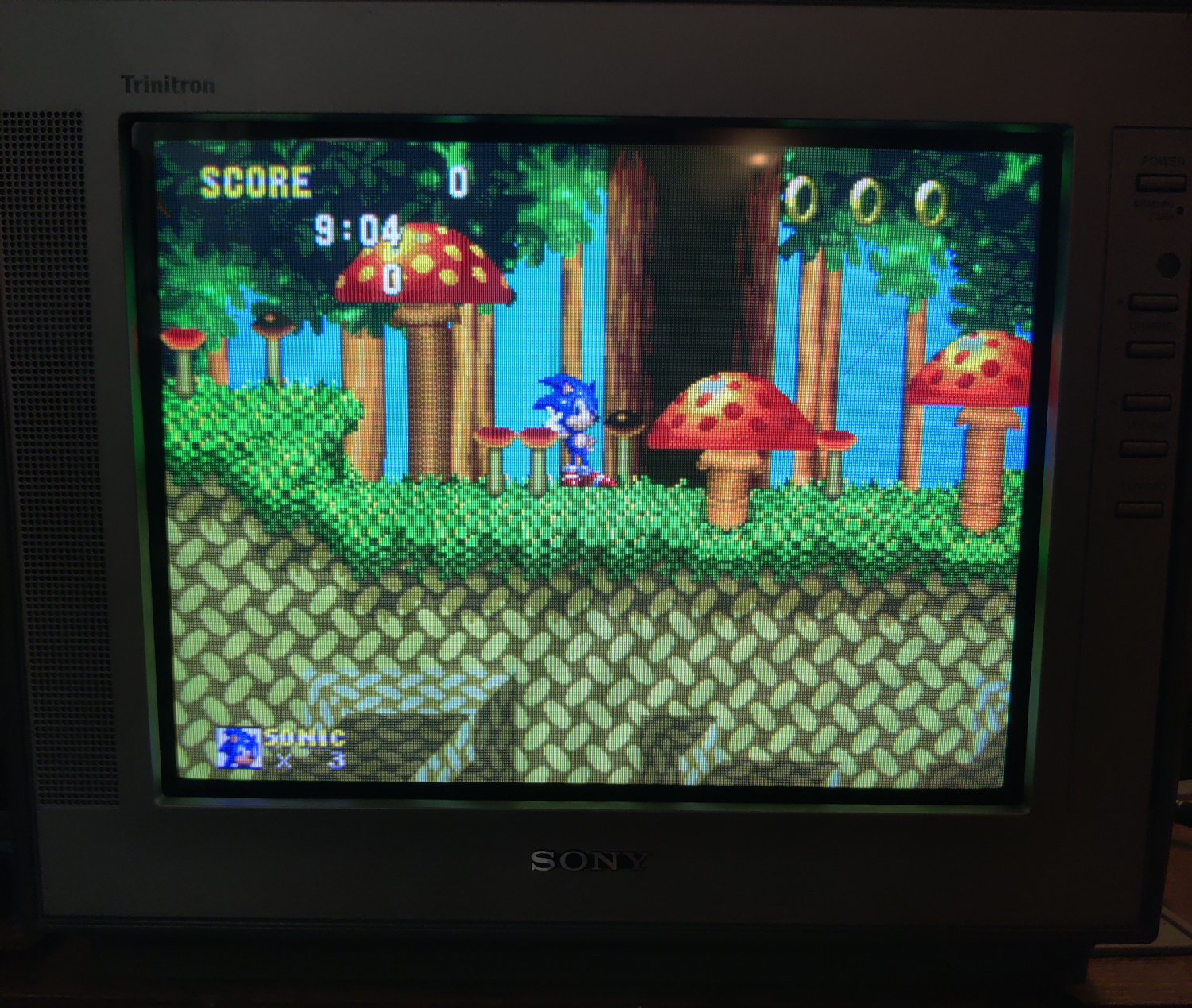
That’s all for the wiring, you should now test your work to ensure that it is all functioning properly.
Step 4: Mounting the SCART port
I used a 3D-printed SCART port panel to cover up any not-so-perfect cutting I did for the port.
To do the actual cutting I drew an outline of the port using the 3D-printed part and then used a sharp razor blade box cutter to cut the outline out. Then I drilled holes to screw into the port using some screws I found that were the right size to thread into the plastic of the SCART port. You can see the final results below.
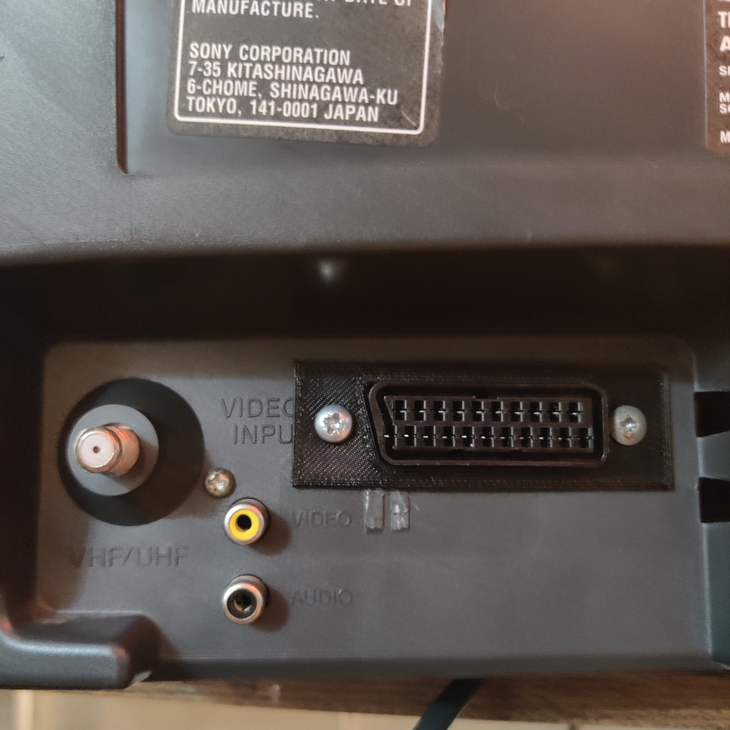
And that’s it for the mod! The picture will appear on Video 1 or Video 2 when you plug in a console and turn it on.
This article is also hosted on Sunthar.com
Back to top