240p Test Suite on a Raspberry Pi for CRT Testing, Calibration and Repair
I wanted a single, portable device for all my CRT repair needs, so I used a spare raspberry pi I had to run the 240p Test Suite. I was unsatisfied with all the guides I found on getting composite output from a raspberry pi, they were all missing something or just no longer worked with the latest emulation distros. I wanted something that accurately outputs 240p content, boots up as fast as possible, and has a simple, flexible UI. After some digging, I decided to use Lakka as the distro, with some key modifications for this use case.
Lakka is a Linux emulation distribution that directly uses RetroArch as its means of running games as well as for UI. There is no fancy EmulationStation-like interface to scroll around in and it has as little bloat as possible. In addition to those benefits, using RetroArch as the means of rendering video allows us to customize the specifics of that output for each core that we want to use. This was the key to getting this to work how I wanted.
This guide will go over how to set this up on a Rapspberry Pi Zero, but it will work with most other Pis as well, with the difference being where to solder the composite video wires. I have notes about other Pis where needed.
There are, however, some Pis that have been confirmed not to work correctly with certain version of Lakka:
- Original Pi 1 with RCA jack does not work at all (hangs at boot logo screen)
- Pi 3 with 64-bit/aarch64 image does not work (MUST use 32-bit/arm). Also note that one the Pi 3s that I have tried there is a weird black graphical glitch in the top right corner.
- Pi Zero 2W with Pi Zero 2 images does not work (MUST use 32-bit/arm Pi 3 image with
dtoverlay=vc4-kms-v3d,cma-384,composite=1change todtoverlay=vc4-kms-v3d,composite=1indistroconfig-composite.txt)
Step 1: Getting Composite Output From Your Pi
All Raspberry Pis can output composite video, but where the signal is output is different depending on the model.
If you get a black screen, or a weird thick, jagged white line and/or shifting video when you boot up your Pi using composite video, you soldered the wires incorrectly.
Pi Zero
For a Raspberry Pi Zero 1, the output is made available via 2 through-holes on the Pi’s PCB. They are labelled by a box around them with the text TV screen printed next to it.
Simply get a spare RCA or BNC cable that you can cut and use for this and solder the center/hot/signal wire to the left and the shield/ground wire to the right when looking at the board with the SD card on the left side. See the photo below.
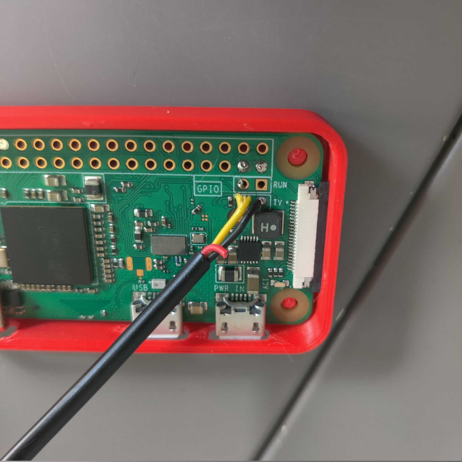
Some Pi Zero 1s have the TV label on the left side of the box and some have it on the right, but where the wires go is not different. The video signal comes from the left side and the ground on the right.
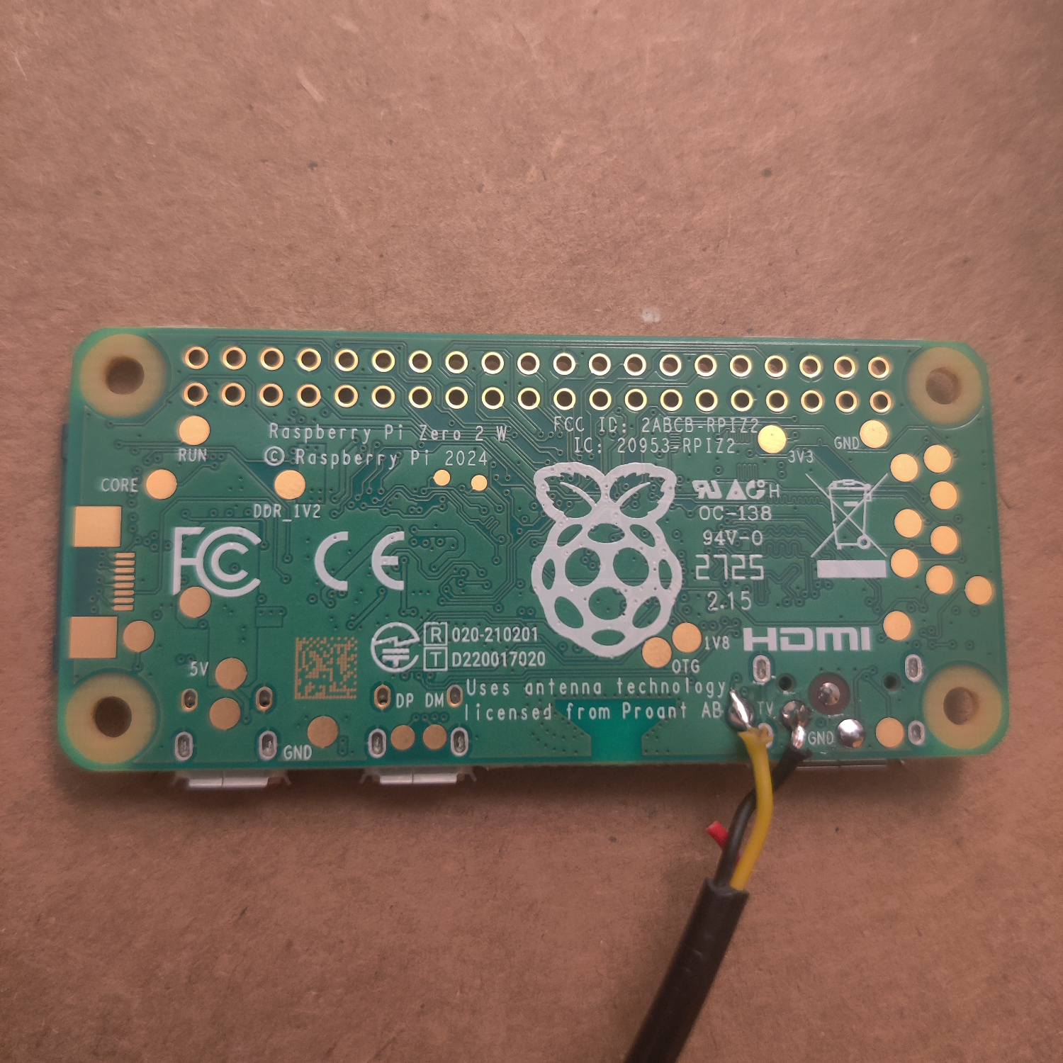
Pi Zero 2
Solder an RCA cable to the TV and GND pads on the bottom of the PCB.
It’s important to solder to the correct pads. The video signal is from the pad to the LEFT of TV and ground is to the right of it. See the following image:
Pi 1 A+/B+ through Pi 4 B
In the case of Pi 1 B+/A+ through 4 B, the 1/8” headphone jack is actually a TRRS AV out jack.
The cable you are using must have the correct polarity, check with a multimeter that the TRRS output is
| Left Audio | Right Audio | Ground | Video |
If it is not, the cable will not work correctly. Most TRRS cables that have RCA connectors on them are not correct and need to be rewired.
You can also purchase the correct cable from adafruit.
Pi 5
The Pi 5 has 2 through-holes on the PCB in a box labelled VID in between the HMDI1 and CAM/DISP 1 ports. Ground is the through-hole closest to the edge, and the video signal is the square pad.
Step 2: Flash Lakka and Configure Composite Video
Each kind of Pi only works with this guide using a specific Lakka image.
Download the following Lakka image for your Pi from their website:
- Pi Zero 1: “for Raspberry Pi Zero / Zero W (arm)”
- Pi Zero 2: “for Raspberry Pi 3 (arm)” The images labelled for Pi zero 2 DO NOT WORK properly
- Pi 1 B+/A+: “for Raspberry Pi (arm)”
- Pi 2: “for Raspberry Pi 2 (arm)”
- Pi 3: “for Raspberry Pi 3 (arm)” the file downloads as Lakka-RPi2.arm-5.0, this is fine
- Pi 4: “for Raspberry Pi 4 (aarch64)” note: I have not tested a pi 4
- Pi 5: “for Raspberry Pi 5 (aarch64)” note: I have not tested a pi 5
Flash the image onto an SD card using one of the following USB flashers (or something you already know how to use):
- Popsicle USB Flasher
- Balena Etcher
- win32diskimager
Once it is done flashing, you’ll need to edit the boot config files to output composite video.
Reinsert the SD card into you computer so you can access the files on the SD card and modify them.
You should see the SD card show up as LAKKA in your file manager.
- Open the SD card partition labelled
LAKKAin your file manager. - Open the file
config.txtin a text editor. - Find the line that has
include distroconfig.txtand comment it out by adding a#to the beginning of the line. - Find the line that has
#include distroconfig-composite.txtand uncomment it by removing the#at the beginning of the line. - Save these changes. Those two lines should now look like this:
#include distroconfig.txt include distroconfig-composite.txt - Next, open the file
cmdline.txtin a text editor. - Add
video=Composite-1:720x480@60ieto the end of the one line in the file and save it. It should look something like this (the UUIDs and other values will likely be different and there may be more than just these parameters in the file):boot=UUID=1704-1837 disk=UUID=b6a5e937-7d11-4142-87f9-3c4a5a54cfa6 quiet console=tty0 video=Composite-1:720x480@60ie - Raspberry Pi Zero 2 only: open
distroconfig-composite.txtand changedtoverlay=vc4-kms-v3d,cma-384,composite=1todtoverlay=vc4-kms-v3d,composite=1by removingcma-384,from that line.
Save those file changes if you haven’t already, and insert the SD card into your pi and plug it into a Composite video monitor or CRT, then power it on.
Let it run and do its thing to finish setting up. Once it’s done and is booted to the Lakka menu, turn off the Pi and take the SD card out.
Step 3: Configuring Lakka for 240p Output
I created these configs to be as close as possible to the output of an actual SNES, NES and Genesis. I loaded the same 240p suite on the Pi and my consoles and went back and forth and adjusted the Pi’s core configs until the pictures were the same size and positioning as my consoles. You can adjust these to your liking, but they should be accurate and thus good for calibration and repair. I also set the Lakka UI layout and scale such that it is usable in 240p with these configs.
Reinsert the SD card into you computer so you can access the files on the SD card and modify them.
NOTE: On Mac or Windows you will have to do this section via SSH if you cannot mount ext3/ext4 filesystems. See this guide on Lakka’s site if you are not using Linux to learn how you can edit files on the ext3/ext4 partition. If you are using Linux, the following guide is exactly what you need to do.
Once you understand and are able to edit text files on the SD card, do the following:
- Open the SD card partition labelled
LAKKA_DISKin your file manager (or access the pi over SSH and you’ll be in this location by default). - Navigate to the folder
.config/retroarch/config/(you may need to access it as root/admin). NOTE: if you are accessing the Pi via SSH, the full path is/storage/.config/retroarch/config/ - Create the folder
QuickNESin.config/retroarch/config/and place the following text in a file calledQuickNES.cfgin theQuickNESfolder you just created (this is the NES core that will be used).aspect_ratio_index = "23" custom_viewport_height = "224" custom_viewport_width = "642" custom_viewport_x = "45" custom_viewport_y = "6" video_fullscreen_x = "720" video_fullscreen_y = "240" xmb_layout = "1" menu_scale_factor = "0.75" - Create the folder
PicoDrivein.config/retroarch/config/and place the following text in a file calledPicoDrive.cfgin thePicoDrivefolder you just created (this is the Genesis/Mega Drive core that will be used). Note that some games do not produce audio properly on some versions of PicoDrive (I personally noticed Sonic and Knuckles and Sonic 2 have this problem), but I chose it because it runs the games the fastest.aspect_ratio_index = "23" custom_viewport_height = "224" custom_viewport_width = "642" custom_viewport_x = "37" custom_viewport_y = "8" video_fullscreen_x = "720" video_fullscreen_y = "240" xmb_layout = "1" menu_scale_factor = "0.75" - Create the folder
Snes9x 2002in.config/retroarch/config/and place the following text in a file calledSnes9x 2002.cfgin theSnes9x 2002folder you just created (this is the SNES core that will be used). I chose 2002 because it performs the best of the Snes9x cores.aspect_ratio_index = "23" custom_viewport_height = "224" custom_viewport_width = "646" custom_viewport_x = "37" custom_viewport_y = "7" video_fullscreen_x = "720" video_fullscreen_y = "240" xmb_layout = "1" menu_scale_factor = "0.75"
Now when you load a rom using one of these three cores, they will correctly display in 240p.
Step 4: Copy 240p Test Suites to the Pi
With your SD card still inserted, download the SNES and Genesis 240p Test Suites from here, rename them to 240p-SNES.sfc and 240p-Genesis.bin (or whatever you want) and copy them to the roms folder on LAKKA_DISK.
Then download the NES 240p Test Suite from here (it’s the file called 240pee.nes), rename it to 240p-NES.nes and copy it to the roms folder.
Finally, add whatever other test roms you want to the roms folder.
Step 5: Connect a Controller and Boot it up
Get a USB controller (and a micro USB to USB A adapter if you’re using a Pi Zero). I used a simple SNES style controller.
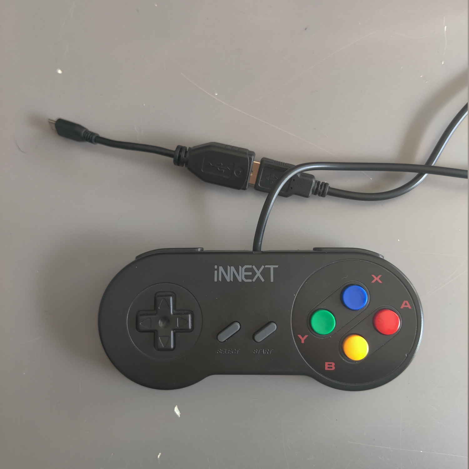
Connect the controller to the pi, connect the Composite video output to a Composite display or CRT, and then connect power.
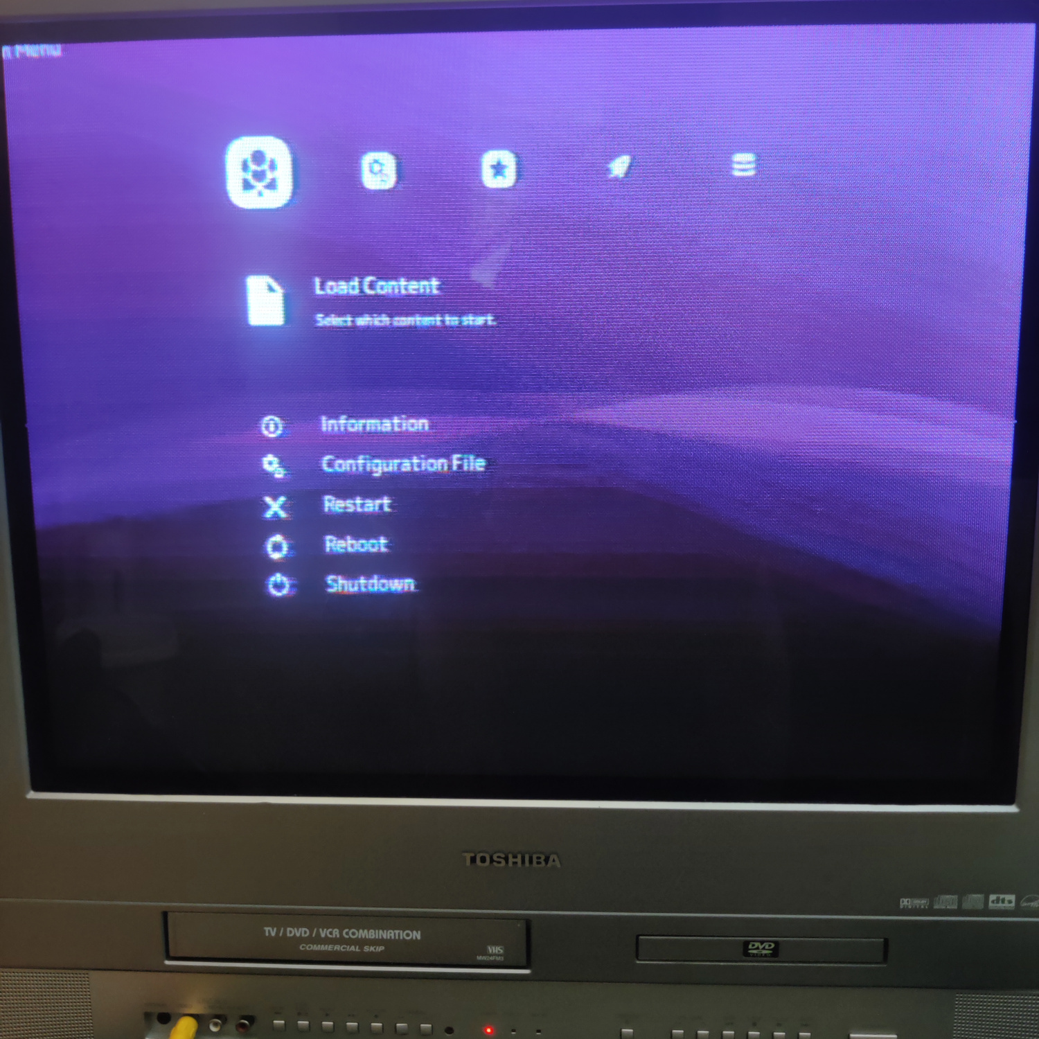
You should see it boot up and display the main menu in 480i mode.
You’re going to want to set the hotkey controller combo to get back to the Lakka menu from running a game.
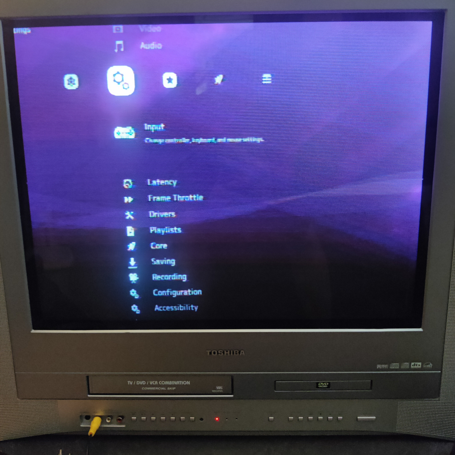
- With your controller, go right to the gears icon and down to
Inputand select it.
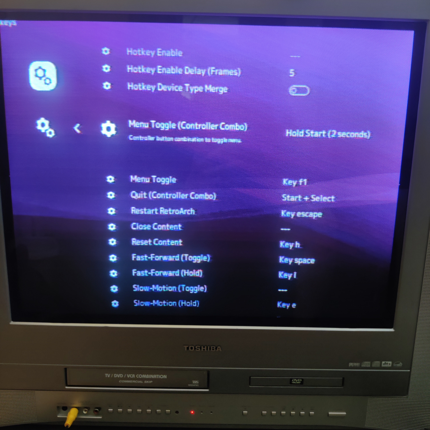
- Go down to
Hotkeysand select it, then go down toMenu Toggle (Controller Combo)and select it. - Choose a combo that makes sense for you and your controller. I selected
Hold Start (2 seconds), but whatever you want is fine so long as your controller actually has the button combo chosen.
Then back out all the way back to the top menu. You can now test out your 240p setup to make sure it’s working right.
- Go down to
Load Contentand select it. - Choose
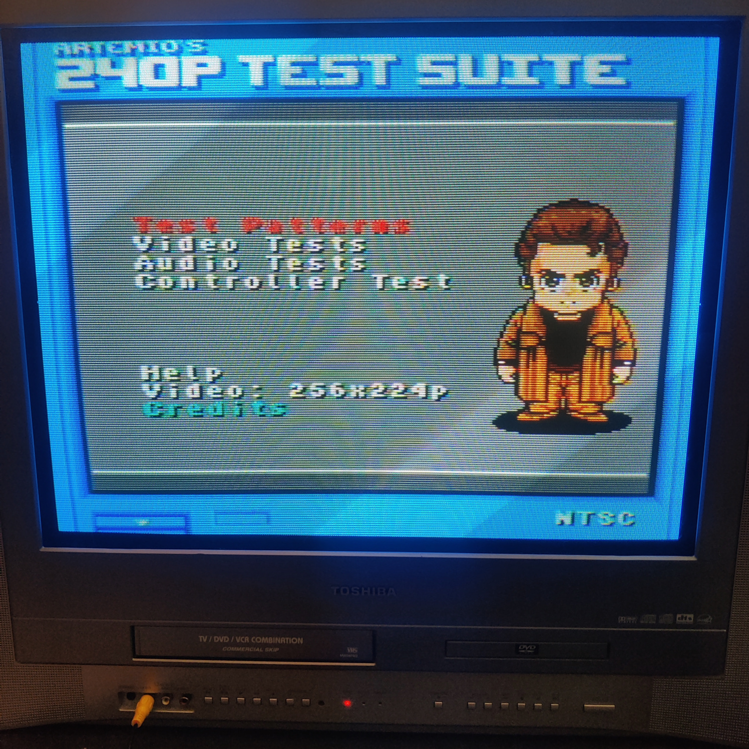
Start Directoryand you should see the roms you put in theromsfolder - Go down to
240p-SNES.sfcand select it, then selectNintendo - SNES / SFC (Snes9x 2002)as the core. This is very important as the settings override was set for this core only. - You should see the 240p Test Suite boot up and be rendering in 240p. If the image is flickering at all (which means it’s in 480i) or if the picture is really narrow and in the center, then you need to go back and make sure you set the configs correctly.
- Press the hotkey controller combo you set and you should see the Lakka menu appear.
- Go down and select
Close Contentand you should be brought back to the main Lakka menu.
If this all went well and looks correct, do the same for the NES 240p suite on the Nintendo - NES / Famicom (QuickNES) core and Genesis 240p on the Sega - MS/GG/MD/CD/32X (PicoDrive) core.
If something looks off with any of them or it’s not rendering in 240p, go back and check that the configuration was done correctly.
To make it easier to access the roms with the correct core, from the menu you access with the controller combo hotkey you can select Add to Favorites and then you will be able to launch the rom from the Lakka main menu’s Favorites section which looks like a Star icon.
And that’s it! You now have a portable CRT testing device :)
If you want my exact setup, you can also download my retroarch.cfg file and replace yours with it. It’s mostly getting rid of menu items that are not necessary for this.
Bonus Step: Get Audio from your Pi
To get analog audio from a Pi Zero or a Pi 5 is a little more involved, and I recommend this guide for that. Alternatively, you can get a USB Audio device that has a headphone output and then get a headphone (1/8” or 3.5mm) to RCA cable. You’d then need to follow the steps below, but for audio_device you’d need to determine what your USB audio device ID is by SSHing into the pi and running aplay -L, so that’s for advanced users. Yet another option is to get an HDMI Audio extractor to use the HDMI audio output, but at that point you might as well get a different Pi.
Here I will cover the few extra steps you need to get audio from your Pi 1 through 4 (this was done on a Pi 1).
- Edit the
config.txtfile in theLAKKApartition of the SD card and uncomment these two lines by removing the#at the beginning (should look like this after):dtparam=audio=on audio_pwm_mode=1 - In
.config/retroarch/retroarch.cfgset theaudio_deviceline to this:audio_device = "default:CARD=Headphones" - In the same config file, make sure
audio_enableis true, like this:audio_enable = "true"
Save those changes and you should now be able to get sound and video from your TRRS cable connected to the Pi.
REMINDER: Your TRRS cable needs to be correctly wired as Left(T), Right(R), Ground(R), Video(S). All TRRS cables with RCA connectors that I have randomly acquired have not been wired this way, so either modify your cable if it is not correct or buy one that is specifically for a Pi.
Files:
Back to top