Sony KV-32FS13 - RGB SCART Mod
This guide will cover how to RGB SCART mod the 32” Sony KV32-FS13. RGB Modding this CRT isn’t too difficult, the hardest part is making the RGB SCART hole for the port imo.
I installed the RGB mod using Sunthar’s guide, which you can see here for additional references.
Step 1: Remove/Replace components
Open up your CRT and pull out the PCB on the left side of the TV (There are 3 in total, the center main board, the left board, and a small power board on the right). You may need to unplug some connectors and pull the other two boards out in order to pull this board out.
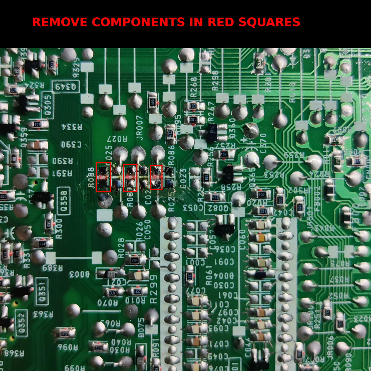
On the bottom of this board, locate R086, R087 and R088 and remove them.
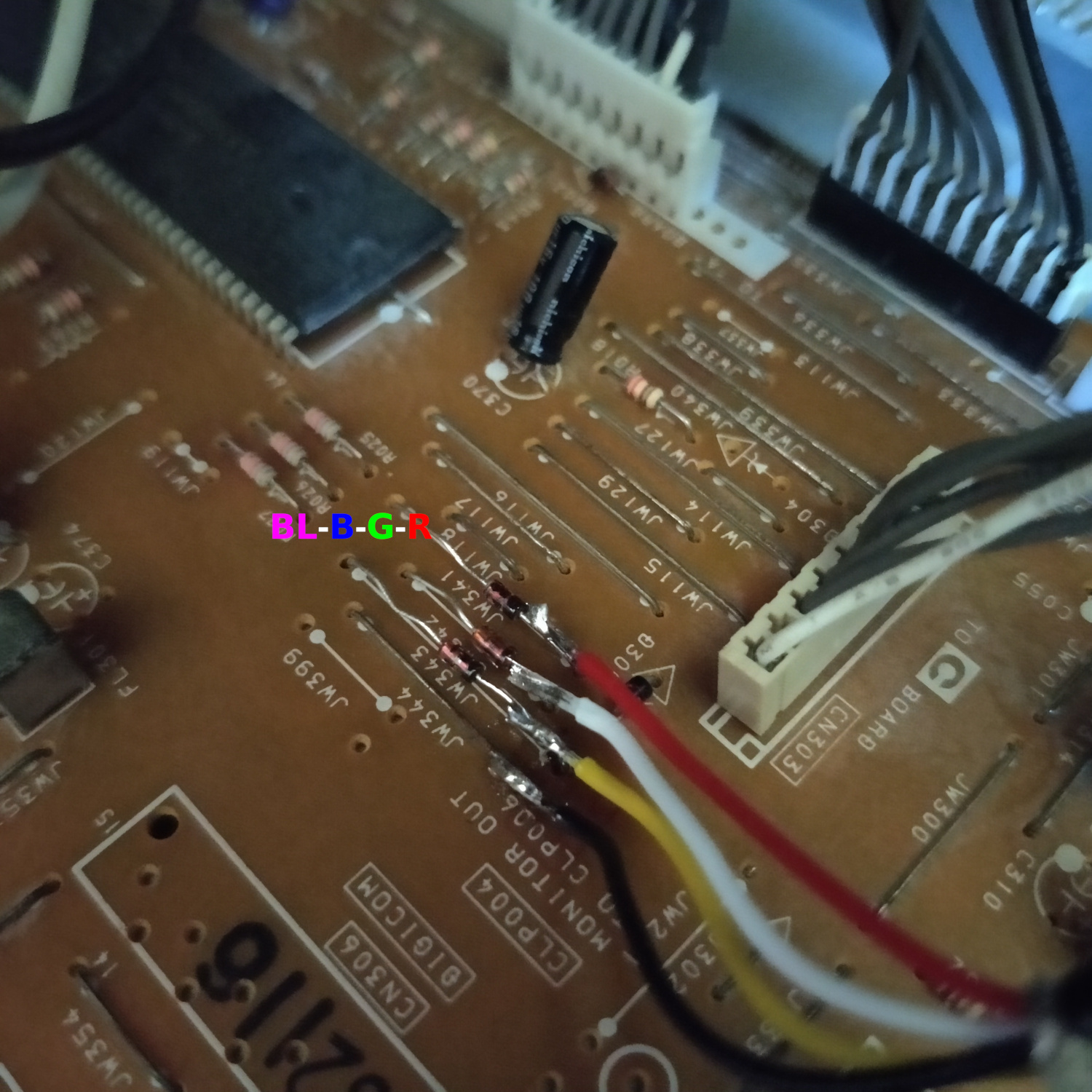
Then locate the three jumper wires shown in the image below and remove them. They are just above the resistors you removed and are labelled on the top as JW341, JW342 and JW343.
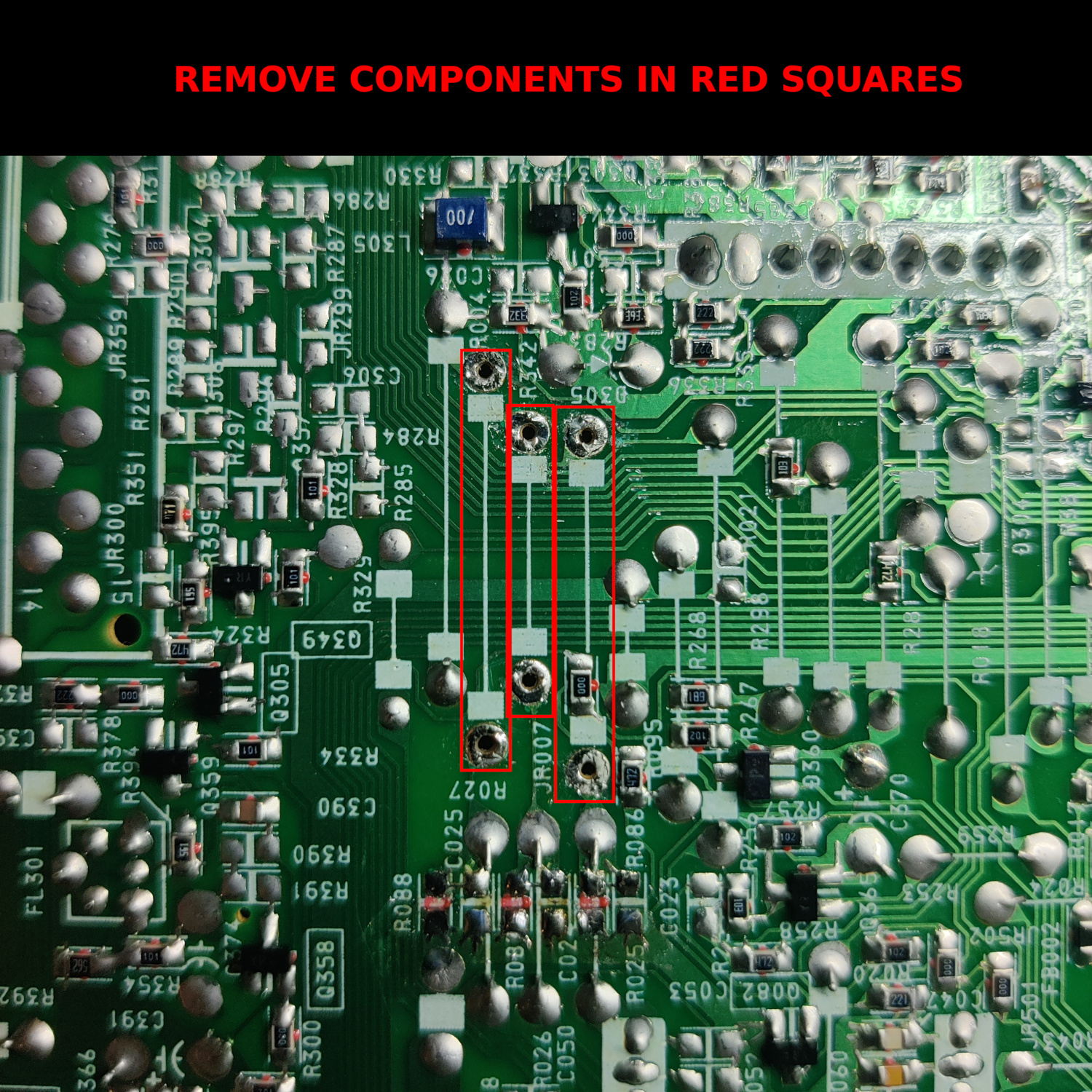
Insert three 1N4148 diodes where those jumpers were removed. Make sure the cathode (the black line on the diode) is on the left side when reading the jumper labels on the top of the board, or on the side closest to the connector CN303.
Step 2: Connect Wires to go to SCART Port
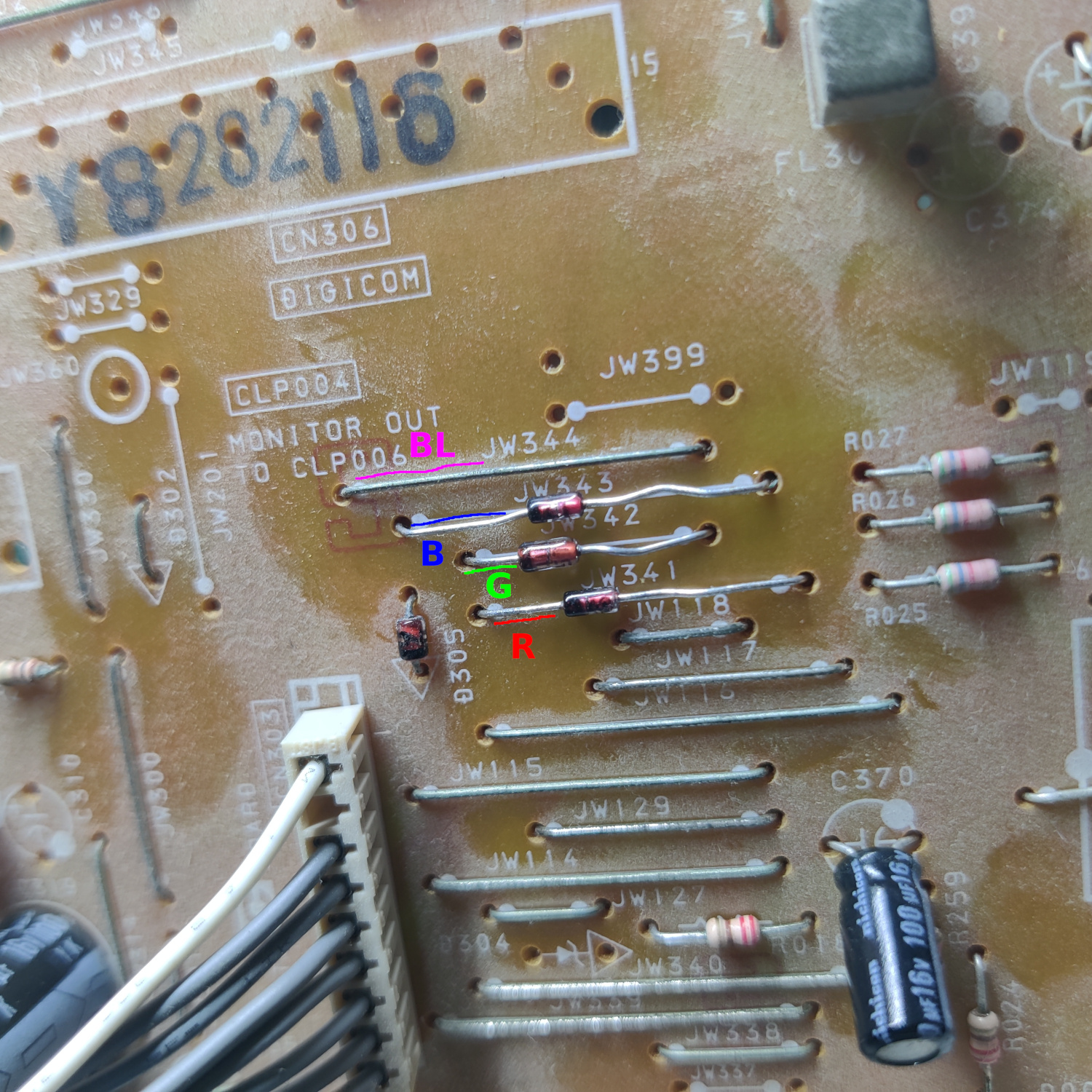
As you can see in the previous image, we will be injecting the RGB and Blanking signals at the cathode sides of the diodes you inserted for RGB, and into the jumper wire for Blanking.
IMPORTANT NOTE: I highly recommend you use shielded cable for the RGB signals, otherwise you will most likely get a lot of noise in your RGB signals that will appear in the video on screen. It looks really bad, like there’s moving noise across the screen. You can get shielded 3-wire cable on the internet pretty easily.
Connect RGB and Blanking leads from your shielded wire to the board as shown below.
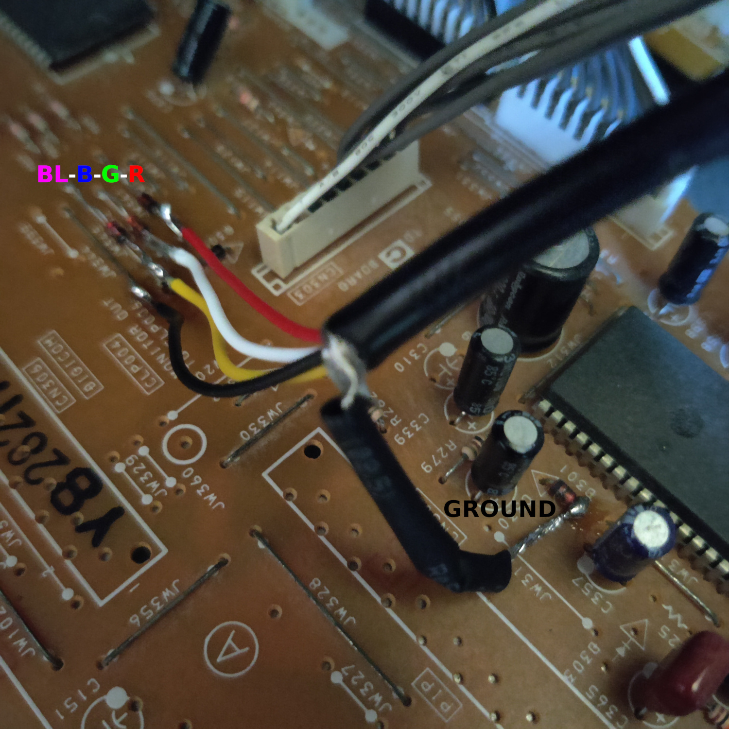
Then connect the ground of your shielded wire to the anode side of D301 as shown below (or any suitable ground point).
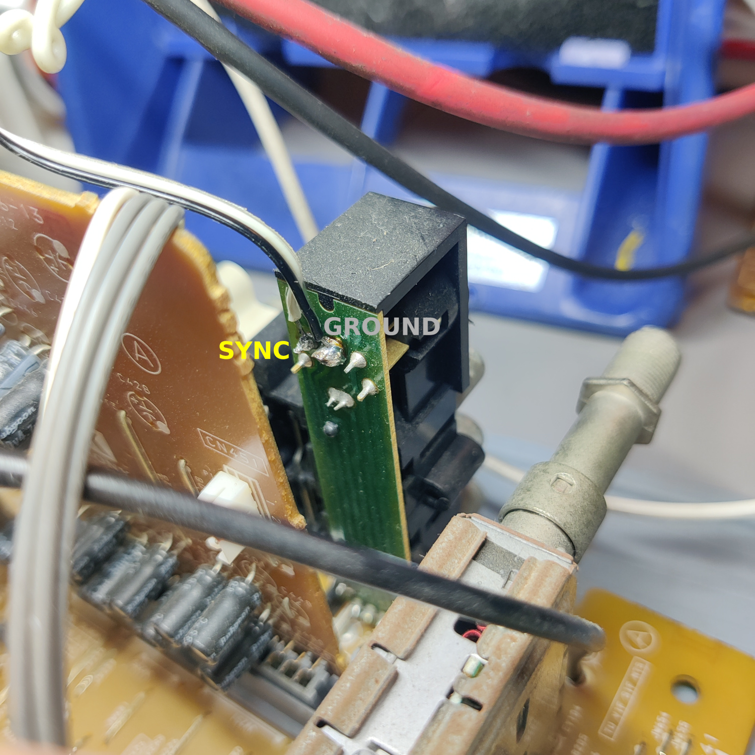
Next, connect wires to the back of the S-Video input jack on the main, center board as shown below. Sync connects to the Y input of the S-Video jack, the other wire is for ground (if using the shielded cable ground this is not necessary but I used it anyway for an extra ground connection).
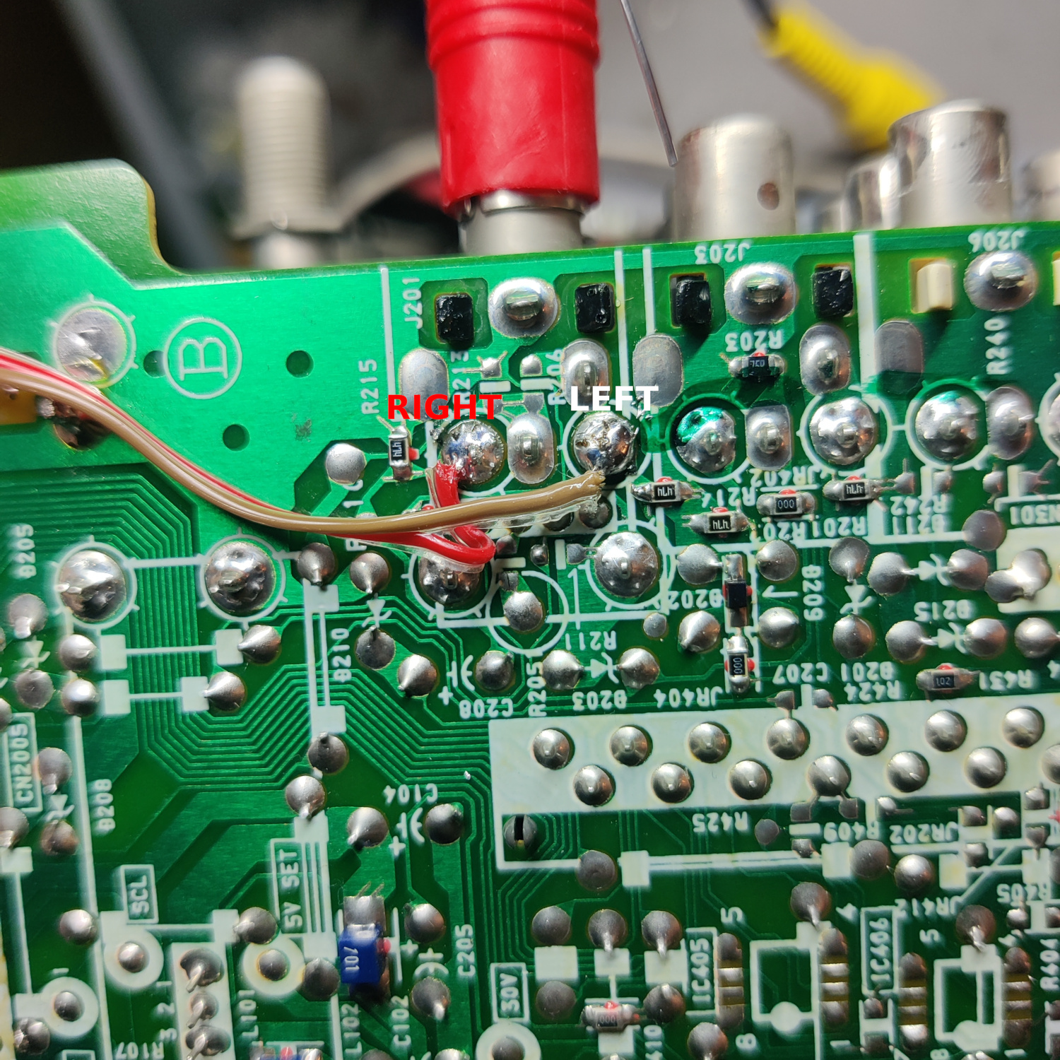
Then connect wires to the underside of the main board S-Video AV jack for your Left and Right Audio.
That’s all the wires you’ll need to connect to your SCART port.
Step 3: Prepare your SCART Port
If you purchased a SCART port from Sunthar, you can follow the instructions on his guide for this section.
CRT Database also has a great guide on creating a clean SCART connector setup, so check that out as well for more info.
If you want to make your own, I used this SCART female socket from AliExpress, which you can find elsewhere. The Ali listing calls it a 21 PINS CS Type Scart Female Socket Connector Jack Female PCB Mount 21 PIN SCART
I then used some prototyping board I had laying around and broke a piece large enough to connect what I needed to it. You can also do this without a board, you’ll just need to make sure to connect your components with enough support that they won’t break off during use/install/movement.
Use the following diagram made using Sunthar’s mux calculator to create your RGB SCART MUX.
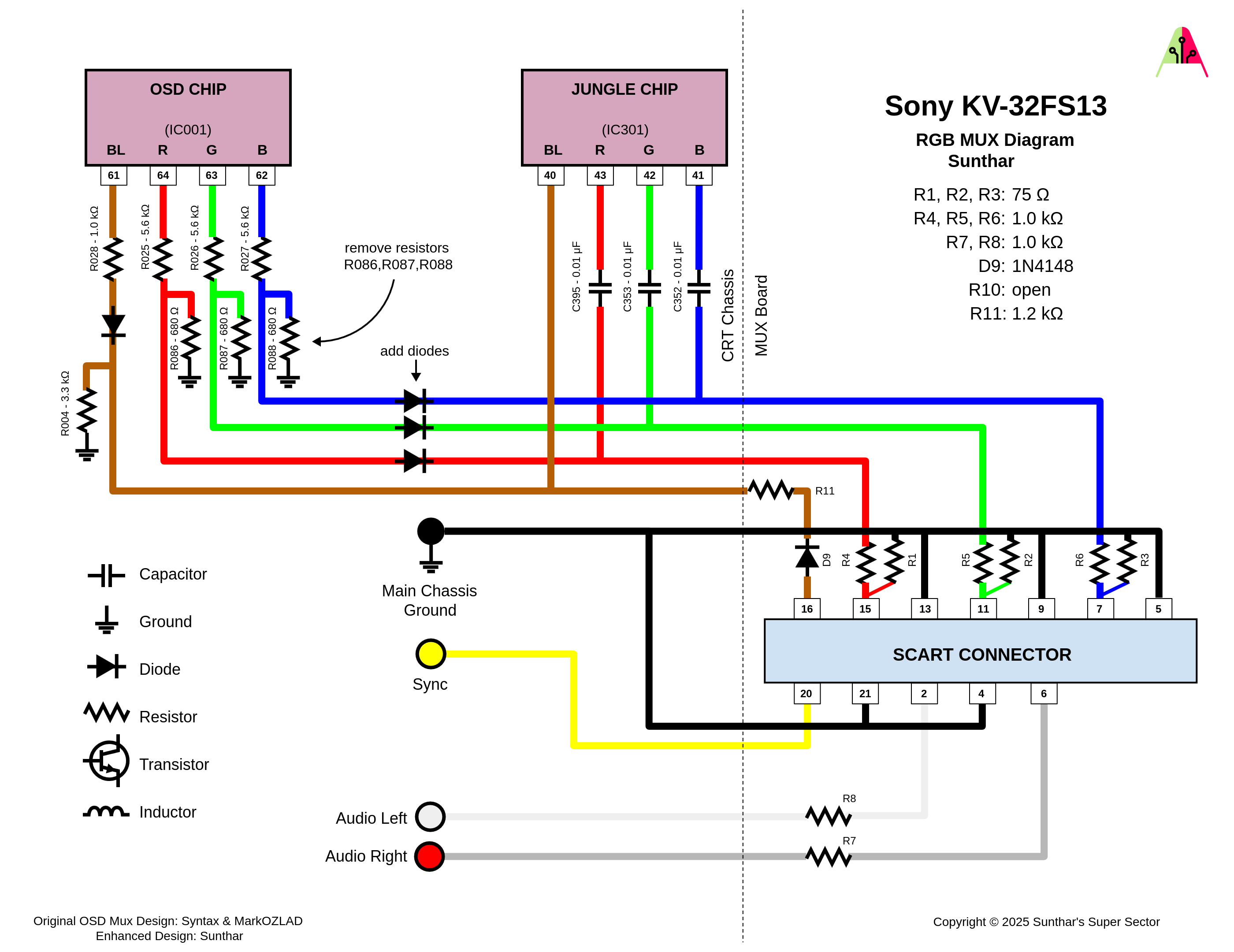
TLDR info is:
- RGB inputs are 75 Ohm terminated then connect to your shielded RGB wires from earlier with 1K Ohm resistors.
- The Blanking input is connected to a 1N4148 diode, then a 1.0K-2.2K Ohm resistor to the blanking jumper from earlier (I used 1.2K Ohms but 1K works fine and Sunthar recommended 2.2K)
- Sync input is connected directly to the S-Video sync wire soldered earlier.
- Audio left and right are connected to the audio wires soldered earlier with 1K Ohm resistors inline.
- Ground is connected to ground through the Shielded RGB cable’s ground, or through another ground, or both.
- MAKE SURE to connect your shielded cable’s ground to the chassis and to the SCART port.
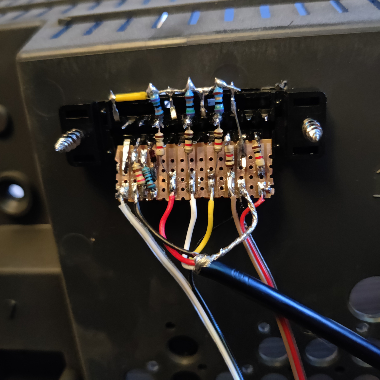
You can see how I made my SCART board in the image below.
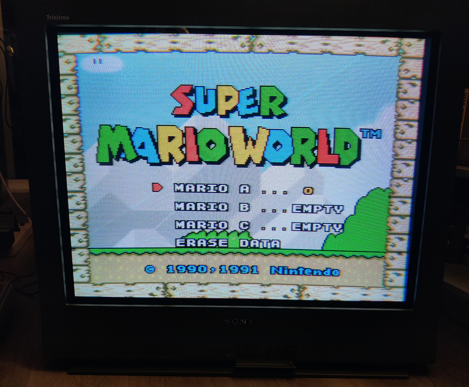
That’s all for the wiring, you should now test your work to ensure that it is all functioning properly.
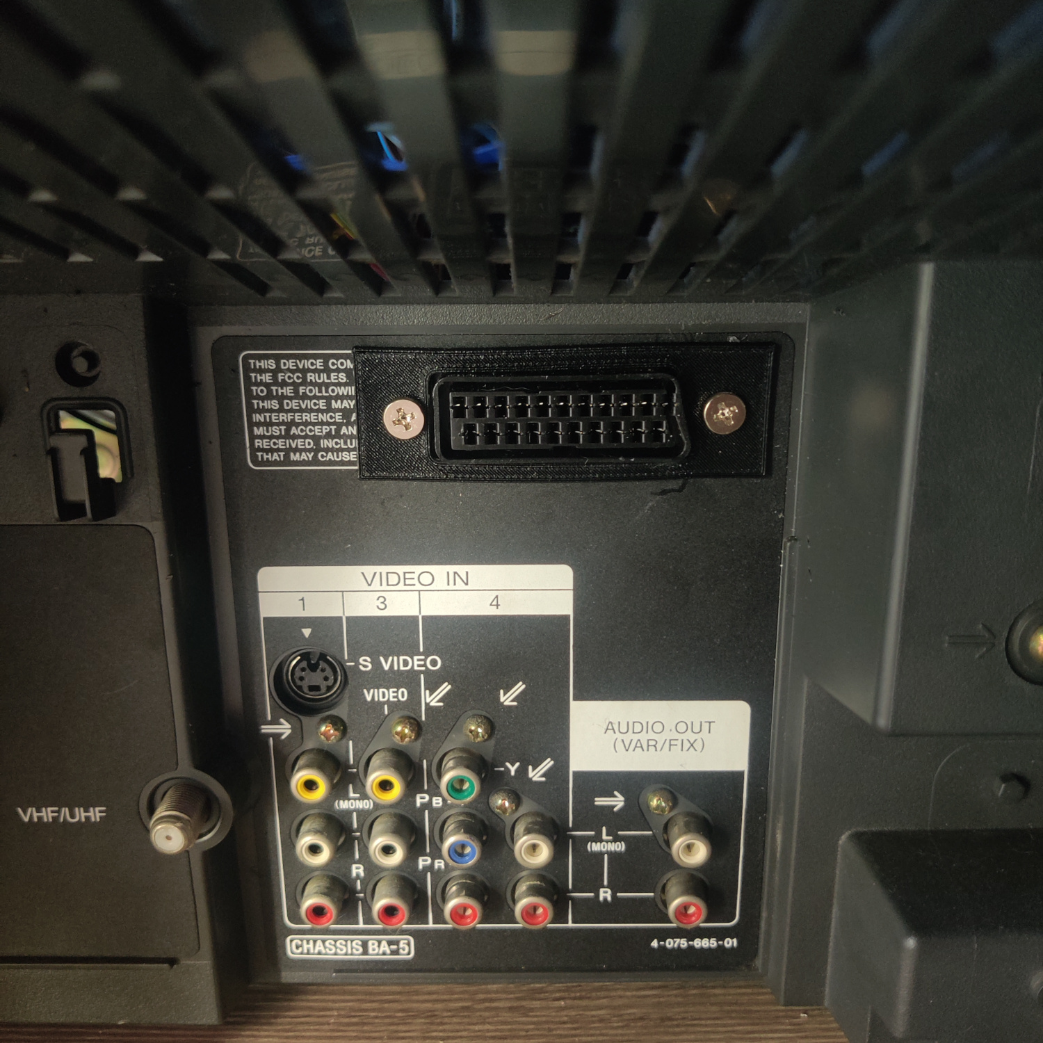
Step 4: Mounting the SCART port
I used a 3D-printed SCART port panel to cover up any not-so-perfect cutting I did for the port.
To do the actual cutting I drew an outline of the port using the 3D-printed part and then used a dremel to cut the outline out. I then needed to use a razor blade to trim the plastic more until it fit snug. Then I drilled holes to screw into the port with using some screws I found that were the right size to thread into the plastic of the SCART port. You can see the final results below.
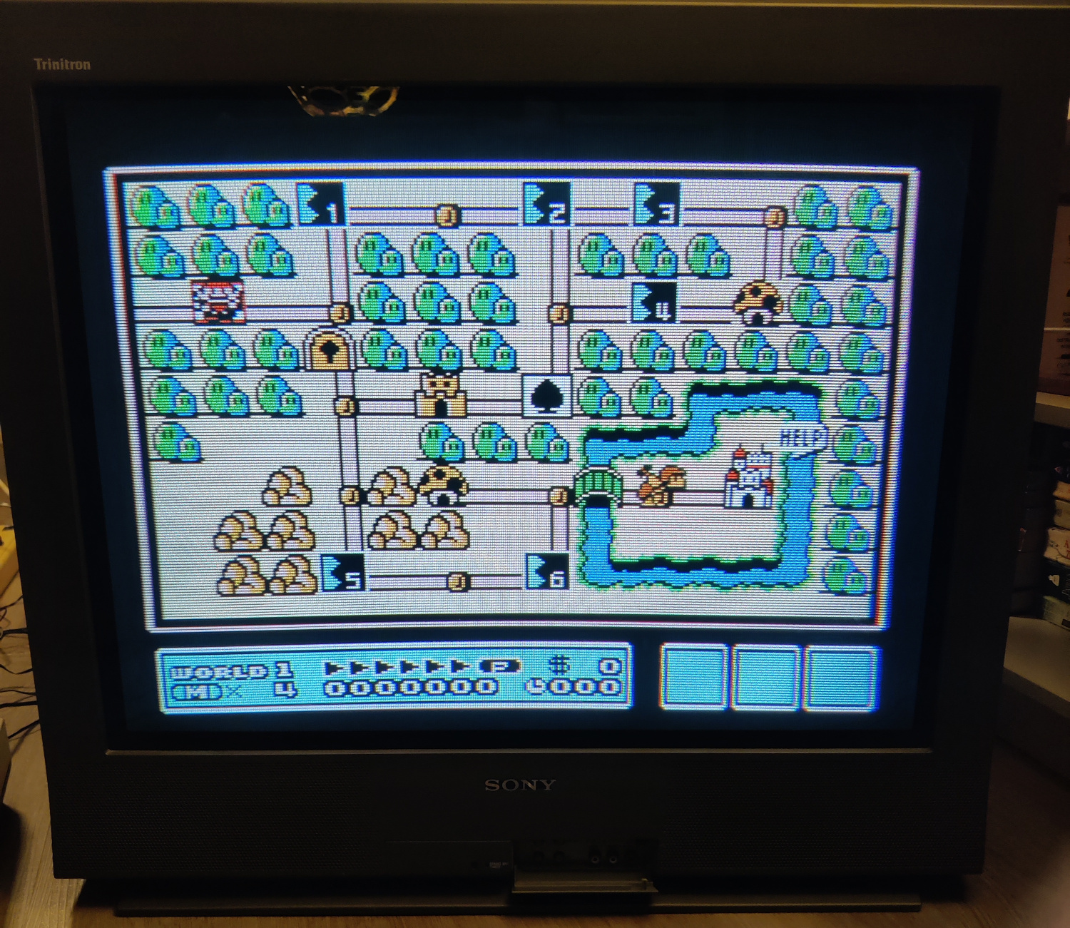
And that’s it for the mod! You’ll need to be on the Video 1 input and the picture will appear when you plug in a console and turn it on. If you go to other video inputs when the SCART connected console is on, you will see a scrolling image because it is not getting sync since sync is tied to input 1. If you want SCART to be a different input you can wire Sync to that input.
This article is also hosted on Sunthar.com
Back to top