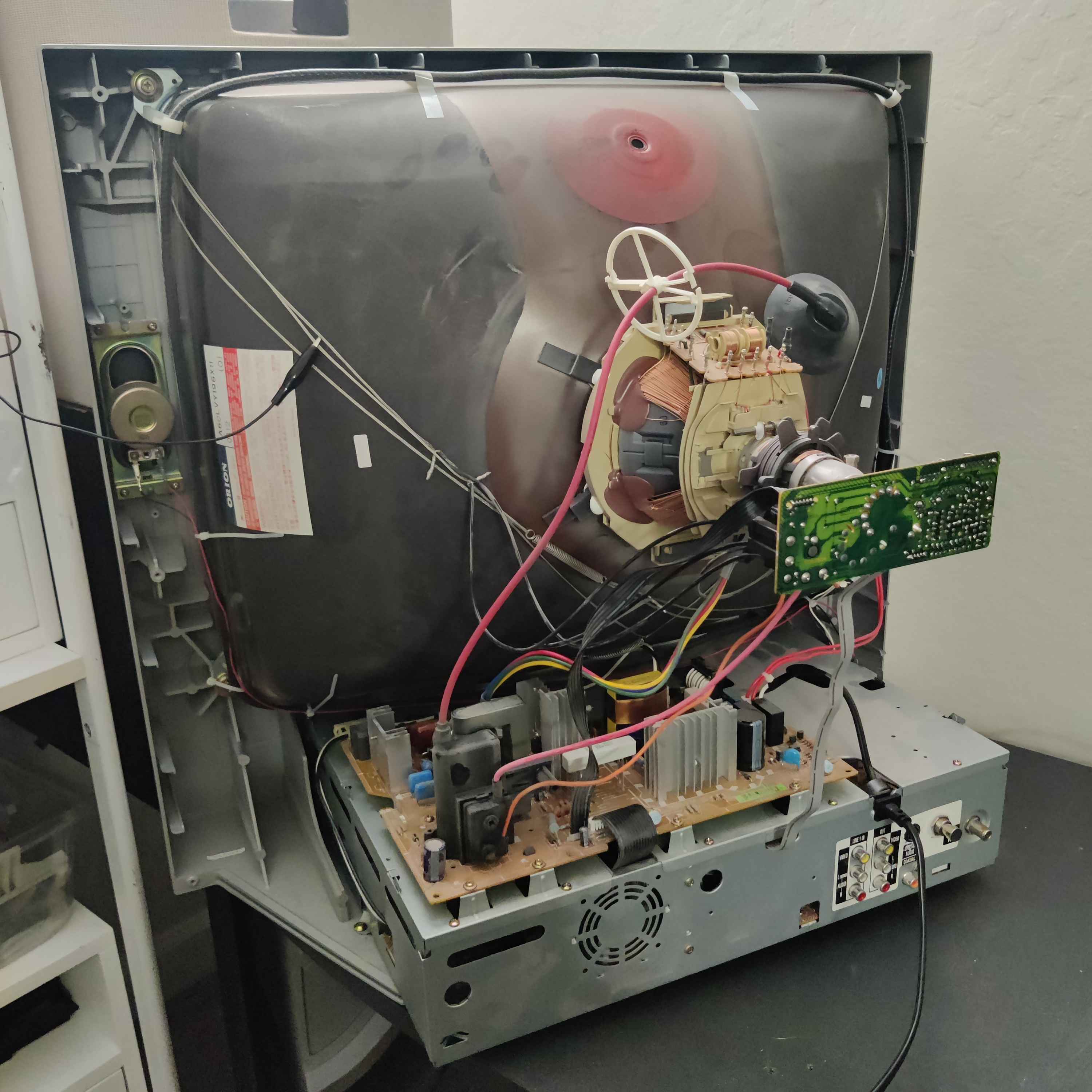
Toshiba MW24FM3 S-Video Mod
Adding S-Video input to this CRT requires injecting the signal at the DVD player, as it outputs S-Video to the VCR PCB which is what handles displaying it on the screen.
To preserve DVD player functionality, you will need some kind of DPDT switch. I used a push button switch made for guitar pedals but there are others.
Installing the mod (and preserving DVD player functionality) is as follows:
- Open the CRT and disassemble it so that you can pull out the PCB case completely. Be sure to properly discharge the anode so you can take the anode off the tube.
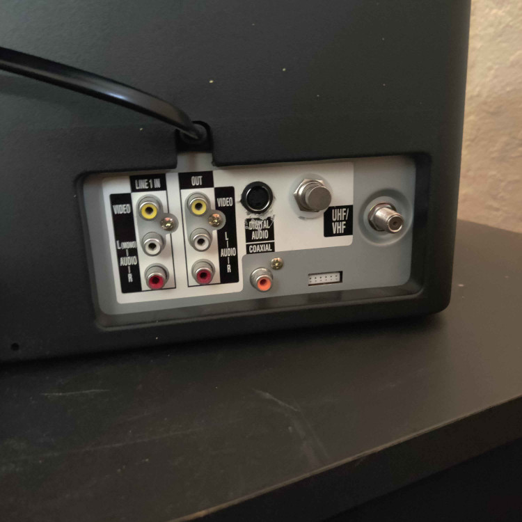
- Drill a hole for the S-Video Jack and mount it to the case near the other AV jacks.
- Drill a hole for the DPDT Switch near the S-Video jack.
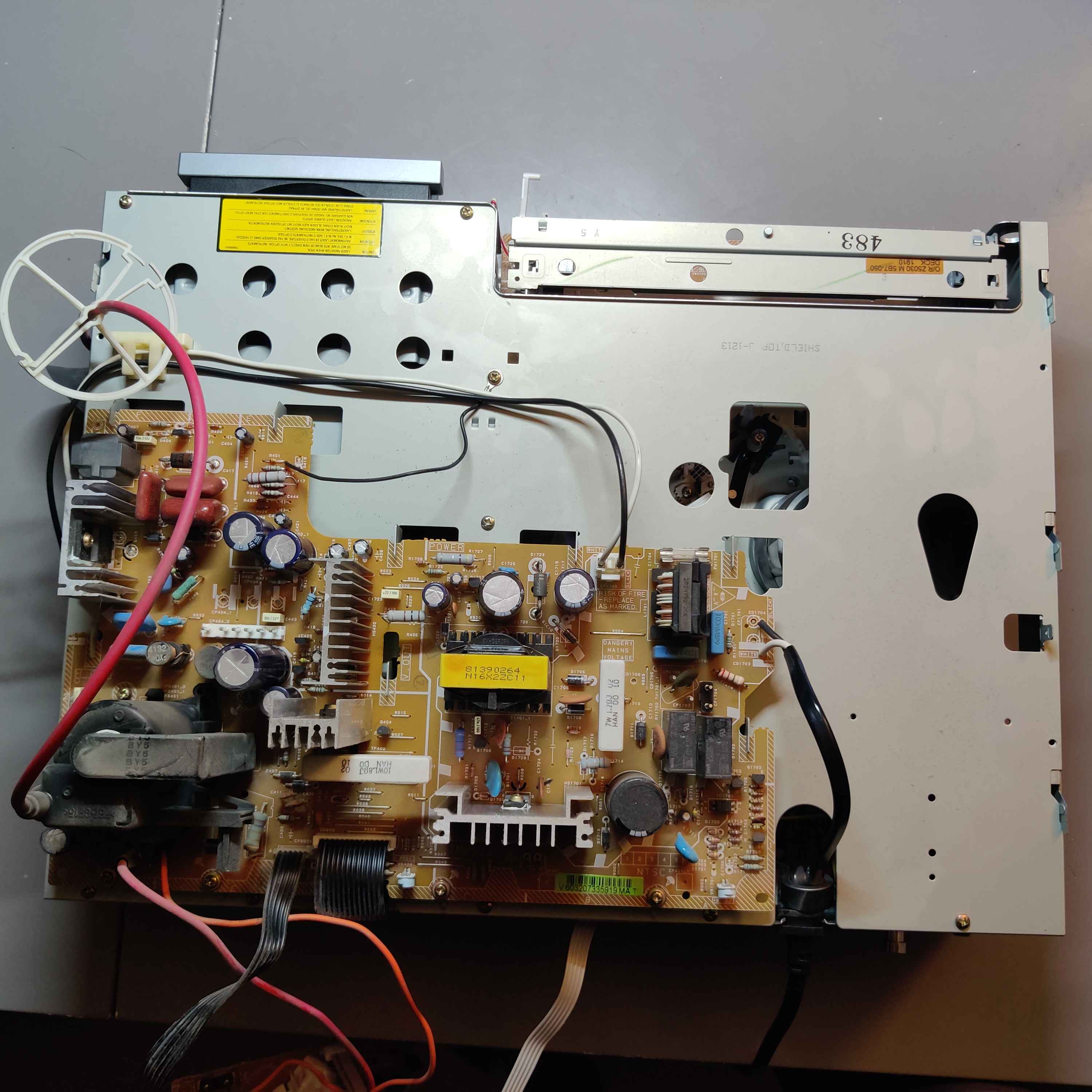
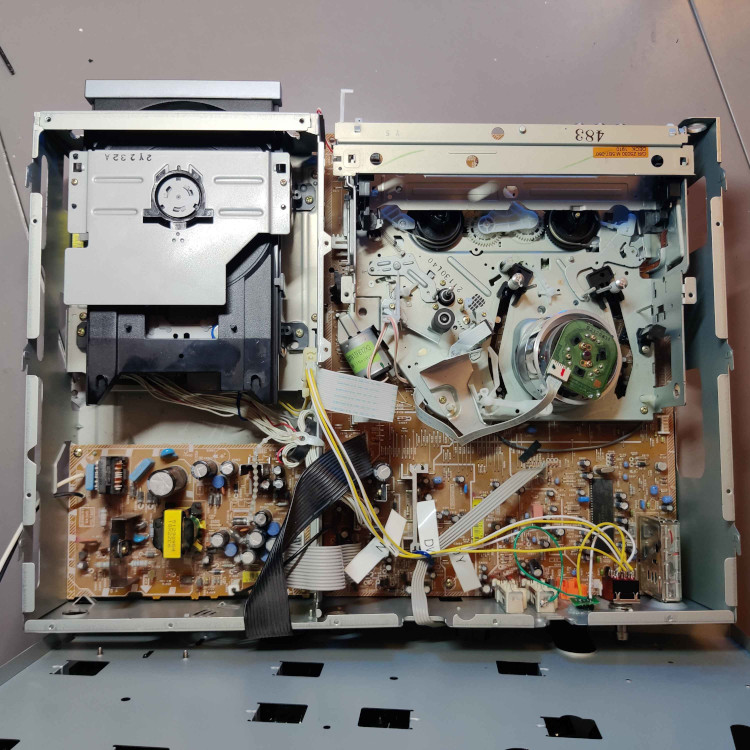
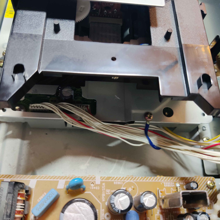
- Remove the DVD player module so that you can access the bottom of the DVD player’s PCB.
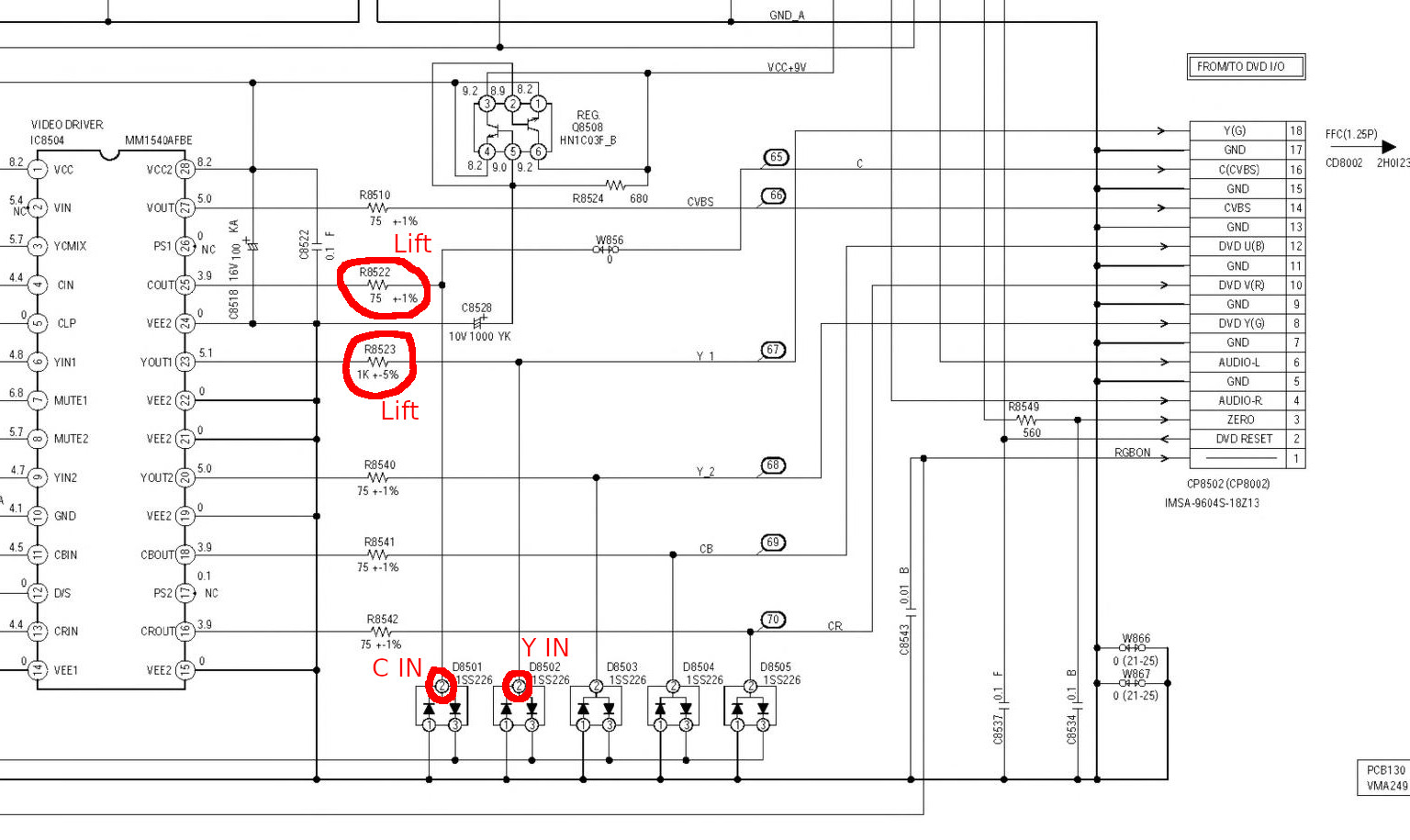
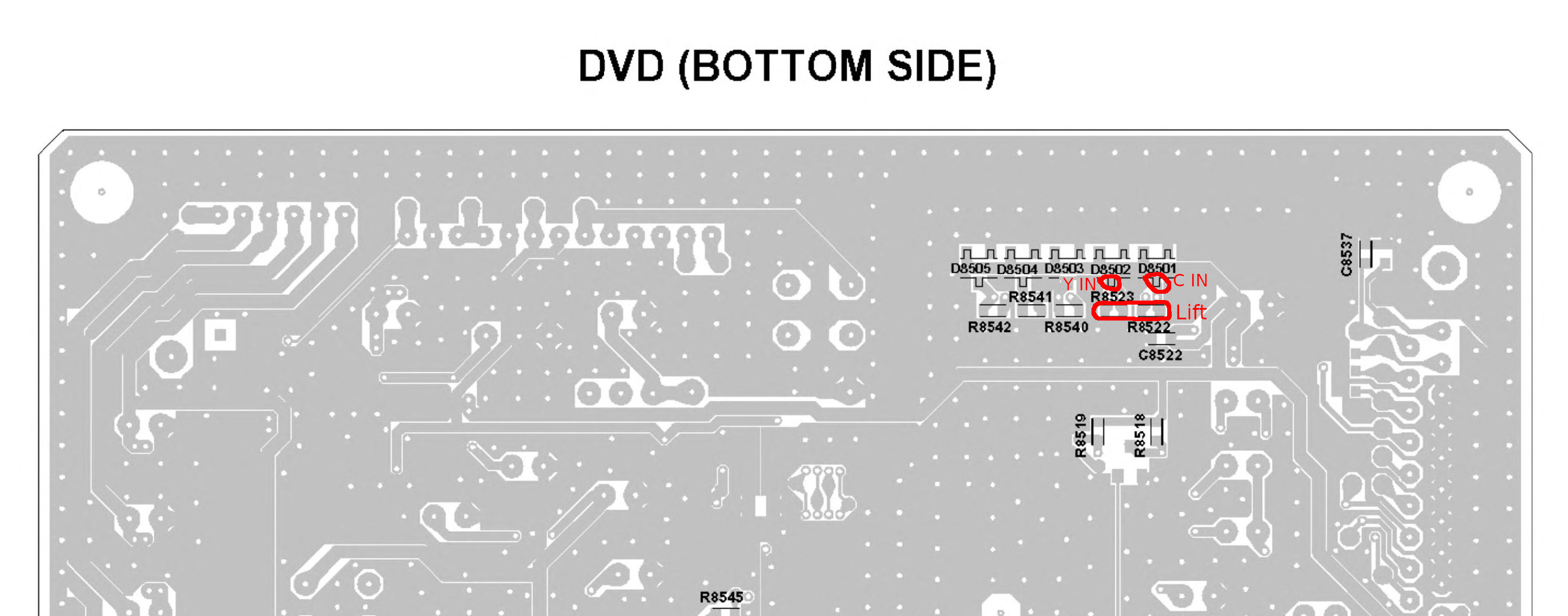
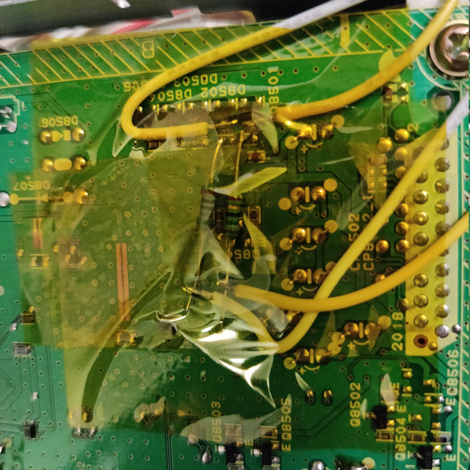
- Remove components R8522 and R8523.
- Solder a 75 Ohm resistor to the left pad of R8522 when viewing it with D8051 above it (see photo below)
- Solder a 1K Ohm resistor to the left pad of R8523 when viewing it with D8052 above it (see photo below)
- Solder wires that are long enough to reach the DPDT Switch to the single terminals of D8051 and D8052 (see photo below)
- Solder wires that are long enough to reach the DPDT Switch to the ends of the two resistors you added (see photo below)
- Reinstall the DVD player module.
- Solder the wire from the 75 Ohm resistor you added to the DVD player (DVD Chroma output) to the leftmost bottom pin of the DPDT switch.
- Solder the wire from the 1K Ohm resistor you added to the DVD player (DVD Luma output) to the rightmost bottom pin of the DPDT switch.
- Solder the wire from D8051 (Chroma input) to the leftmost center pin of the DPDT switch.
- Solder the wire from D8052 (Luma Input) to the rightmost center pin of the DPDT switch. .
- Solder a wire from the S-Video input jack’s Chroma (C) lead to the leftmost top pin of the DPDT switch.
- Solder a wire from the S-Video input jacks Luma (Y) lead lead to the rightmost top pin of the DPDT switch.
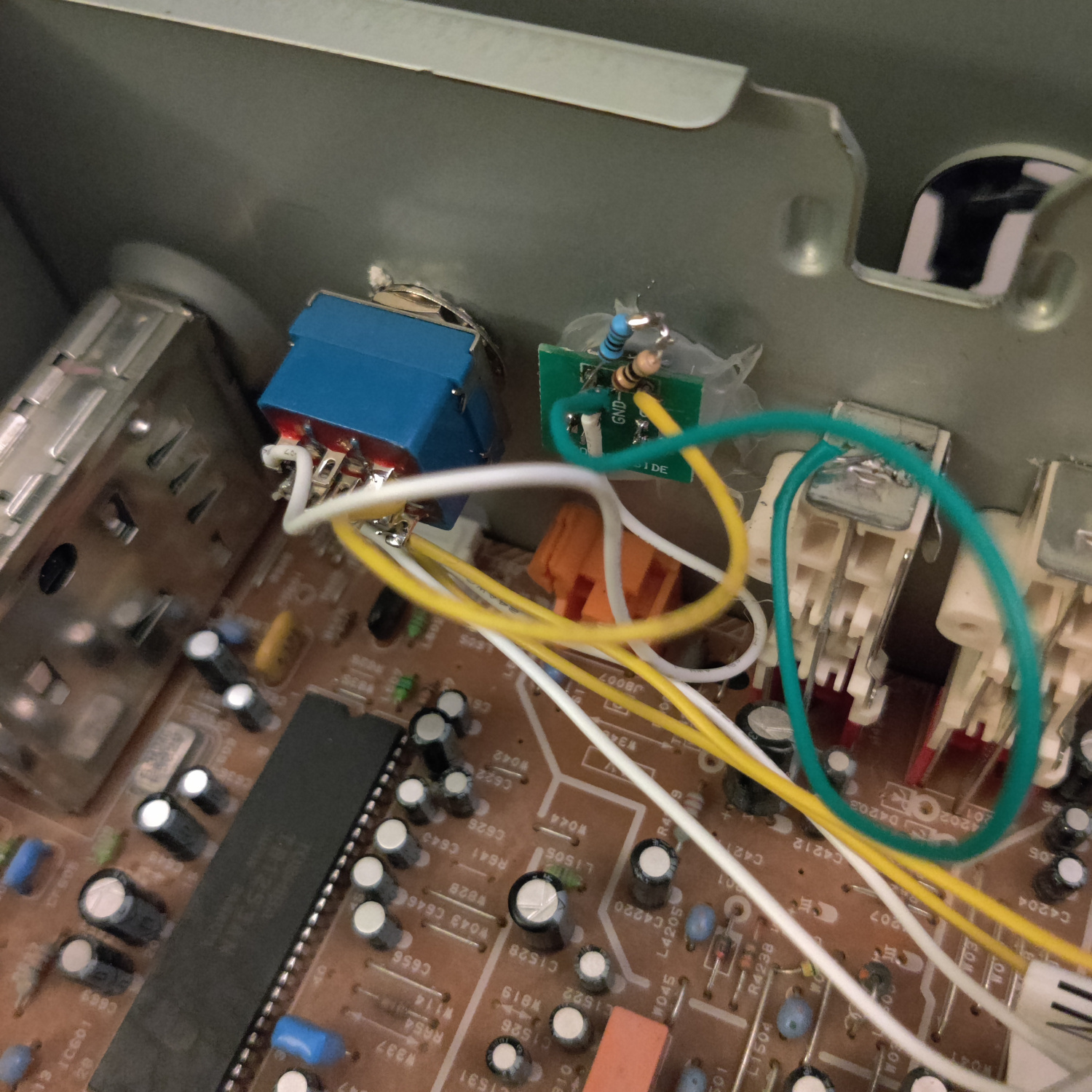
- Solder a wire to ground, either directly to the chassis or find a ground on the PCB to solder to.
- Connect the ground wire to the ground of the S-Video jack.
- Solder a resistor that is around 83 Ohms (I used a 75 Ohm and a 10 Ohm in series) from ground to the S-Video Luma (Y) pin.
That’s it. You don’t need to 75ohm terminate the Chroma signal on the S-Video jack because the VCR PCB where the signal is injected already has termination resistors.
The reason an 83 Ohm resistor is used to terminate the Luma signal is because the VCR PCB has an 820 Ohm termination resistor on the Luma signal trace, and by having around 83 Ohms in parallel with that resistor we get a termination resistance of around 75 Ohms when the S-Video input is used. The DVD player expects 820 Ohm termination and not 75 Ohm termination for Luma, so we can’t just replace the 820 Ohm resistor with a 75 Ohm. Plus this makes it so we don’t have to take the VCR PCB out at all.
Now turn on the CRT and switch to the DVD player using the remote or the buttons on the TV, you should see either the DVD menu or the S-Video signal you are injecting. Toggle the DPDT switch in the back to change which source you see when in the DVD mode of the TV.
If you don’t want to preserve the DVD player functionality, you can simply connect the wires from D8051 and D8052 straight to the S-Video connector instead of to the center of the DPDT switch, and you also don’t need to add the resistors to the DVD PCB.
This article is also hosted on Sunthar.com
Back to top