<?xml version="1.0" encoding="utf-8"?><feed xmlns="http://www.w3.org/2005/Atom" ><generator uri="https://jekyllrb.com/" version="3.10.0">Jekyll</generator><link href="http://manadream.blog/feed.xml" rel="self" type="application/atom+xml" /><link href="http://manadream.blog/" rel="alternate" type="text/html" /><updated>2026-04-20T16:08:23+00:00</updated><id>http://manadream.blog/feed.xml</id><title type="html">manadream electronics &amp;amp; game dev blog</title><subtitle>various notes, info, opinions and ideas relating to game dev, retro console modding, CRTs and electronics in general.</subtitle><entry><title type="html">Memorex MT2024 / Haier 21F7A-P / Durabrand BH2004D / Insignia NS-13CTV Service Menu Access</title><link href="http://manadream.blog/2026/04/17/memorex-mt2024-haier-21f7a-p-durabrand-bh2004d-insignia-ns-13ctv-service-menu-access.html" rel="alternate" type="text/html" title="Memorex MT2024 / Haier 21F7A-P / Durabrand BH2004D / Insignia NS-13CTV Service Menu Access" /><published>2026-04-17T00:00:00+00:00</published><updated>2026-04-17T00:00:00+00:00</updated><id>http://manadream.blog/2026/04/17/memorex-mt2024-haier-21f7a-p-durabrand-bh2004d-insignia-ns-13ctv-service-menu-access</id><content type="html" xml:base="http://manadream.blog/2026/04/17/memorex-mt2024-haier-21f7a-p-durabrand-bh2004d-insignia-ns-13ctv-service-menu-access.html"><![CDATA[<p>The service manual lists the remote button combo to get into the service menu for these sets as “MUTE” -&gt; “CALL” -&gt; “-/–“ -&gt; “CALL” -&gt; “MUTE” which is misleading because “CALL” is NOT the button labeled “RECALL”.</p>

<p>The “CALL” button label is actually referring to the button labelled “DISPLAY”.</p>

<p>So the combo is “MUTE” -&gt; “DISPLAY” -&gt; “-/–“ -&gt; “DISPLAY” -&gt; “MUTE”.</p>

<p>I was trying to get into the service menu for a <a href="https://crtdatabase.com/crts/memorex/memorex-mt2024">Memorex MT2024</a> and I kept interpreting “CALL” as referring to the button named “RECALL” on the remote, which you can see below.</p>

<p><img src="/assets/img/IMG_20260417_205200.jpg" alt="Memorex MT2024 Remote" /></p>

<p>After trying several times, it seemed odd to me that the sequence would include the “RECALL” button as it causes the screen to go blank and switch to another channel and pressing buttons during this does nothing, it just seemed wrong. So I tried pressing a different button for “CALL” because I wasn’t convinced that meant the “RECALL” button, and pressing “DISPLAY” worked!</p>

<p><img src="/assets/img/IMG_20260417_211135.jpg" alt="Memorex MT2024 Service Menu" /></p>

<p>The remote for the Durabrand BH2004D is the same layout <a href="https://crtdatabase.com/crts/durabrand/durabrand-bh2004d">as you can see here</a>. The Insignia remote has a lot more buttons, as can be seen in the user manual <a href="https://crtdatabase.com/crts/insignia/insignia-ns-13ctv">available here</a>, and notably it is missing the “–/-“ button, but the service manual for this set has the exact same combo listed as the other sets. I don’t have the set and remote to verify this, but I suspect the possible replacements for “–/-“ are “10+”, “TIME”, “EXIT”, “PROGRAM” or “D.CALL”. If you have this set and remote and are able to get into the service menu, please send me a message using the contact form <a href="https://manadream.shop/">on my store website</a> so I can update this article with the correct combo.</p>]]></content><author><name></name></author><category term="CRT" /><summary type="html"><![CDATA[The service manual lists the remote button combo to get into the service menu for these sets as “MUTE” -&gt; “CALL” -&gt; “-/–“ -&gt; “CALL” -&gt; “MUTE” which is misleading because “CALL” is NOT the button labeled “RECALL”.]]></summary></entry><entry><title type="html">JVC C-13111 - RGB SCART Mod</title><link href="http://manadream.blog/2026/04/13/jvc-c-13111-rgb-scart-mod.html" rel="alternate" type="text/html" title="JVC C-13111 - RGB SCART Mod" /><published>2026-04-13T00:00:00+00:00</published><updated>2026-04-13T00:00:00+00:00</updated><id>http://manadream.blog/2026/04/13/jvc-c-13111-rgb-scart-mod</id><content type="html" xml:base="http://manadream.blog/2026/04/13/jvc-c-13111-rgb-scart-mod.html"><![CDATA[<p>This guide will cover how to RGB SCART mod the JVC C-13111. It will be necessary to remove or at least pull out the main board to do this mod.</p>

<p><img src="/assets/img/IMG_20260413_152454.jpg" alt="set" /></p>

<h2 id="step-1-removereplace-components">Step 1: Remove/Replace components</h2>

<p>Open up your CRT and pull out the large PCB in the bottom center of the TV. There are some clips at the front where the buttons are, it is easiest to remove the board if it is at an upward angle as this disengages those clips more.</p>

<p>On the bottom of this board, locate R738, R740, R742 and remove them. They are located near IC701 which is at the front of the TV. The service manual, available on <a href="https://sector.sunthar.com/guides/crt-rgb-mod/jvc-c-13110.html#manuals-and-datasheets">Sunthar’s page for the C-13310</a> has a picture that shows the location of them.</p>

<h2 id="step-2-connect-wires-to-go-to-scart-port">Step 2: Connect Wires to go to SCART Port</h2>

<p>RGB wires will be soldered to the side of C801, C802 and C803 that is not connected to IC201. See the image below, R goes to C801 left side, G goes to C802 top side, and B goes to C803 top side when viewing the PCB such that the majority of the component labels are facing you.</p>

<p>The Blanking wire solders to the wire bridge that is installed where L705 would go. See photo below.</p>

<p><img src="/assets/img/IMG_20260408_171222.jpg" alt="RGB and Blanking" /></p>

<p>Connect Sync to the center pin of the yellow composite input in the back.</p>

<p>Connect the Left and Right audio wires both to the negative (-) side of C651, near the audio input in the back.</p>

<p>Connect the ground wire(s) from the mux board to any suitable ground point on the board (I used jumper W148 near the audio and video inputs in the back).</p>

<p>See the photo below for the wiring of these connections.</p>

<p><img src="/assets/img/IMG_20260408_171135.jpg" alt="Sync, Audio and Ground" /></p>

<p>That’s all the wires you’ll need to connect to your SCART port.</p>

<h2 id="step-3-prepare-your-scart-port">Step 3: Prepare your SCART Port</h2>

<p>Use the following MUX diagram to create your RGB SCART MUX. DO NOT USE THE ONE FOR THE C-13110 ON SUNTHAR’S SITE! It does not have the correct values to get the best signal for this set. Specifically, you need to terminate the RGB lines with 220 ohms instead of 70 ohms to get the best signal. Sunthar has noted that this jungle chip works better with 220 Ohm termination resistors for other sets that use this same jungle chip <a href="https://sector.sunthar.com/guides/crt-rgb-mod/samsung-cxf0933.html#increasing-rgb-termination-resistance">here</a>.</p>

<p><img src="/assets/img/RGB_MUX_Diagram_JVC_C-13111.png" alt="RGB MUX" /></p>

<p>If you purchased a SCART port from Sunthar, you can follow the instructions on <a href="https://sector.sunthar.com/guides/crt-rgb-mod/jvc-c-13110.html#step-3-build-your-mux-board">his site</a> for this section. IMPORTANT NOTE: The MUX diagram for the C-13110 is not correct for the C-13111, use the one shown above for the correct resistor values.</p>

<p>CRT Database also has a <a href="https://crtdatabase.com/modding/wiring-and-installing-a-scart-connector">great guide</a> on creating a clean SCART connector setup, so check that out as well for more info.</p>

<p>If you want to make your own, you can use <a href="https://www.aliexpress.us/item/3256807009901234.html">this</a> SCART female socket from AliExpress, which you can find elsewhere. The Ali listing calls it a <code class="language-plaintext highlighter-rouge">21 PINS CS Type Scart Female Socket Connector Jack Female PCB Mount 21 PIN SCART</code></p>

<p>Then you can use some prototyping board or solderable breadboard to hold the components. You can also do this without a board, you’ll just need to make sure to connect your components with enough support that they won’t break off during use/install/movement.</p>

<p>TLDR info for making your own is:</p>

<ul>
  <li>RGB inputs are 220 Ohm terminated then connect to your RGB wires from earlier with 1K Ohm resistors.</li>
  <li>The Blanking input is connected to a 1N4148 diode, then a 2.2K Ohm resistor to the blanking wire from earlier.</li>
  <li>Sync input is connected directly to the sync wire soldered earlier.</li>
  <li>Audio left and right are connected to the audio wires soldered earlier with 1K Ohm resistors inline.</li>
  <li>Ground is connected to the ground wires soldered earlier.</li>
</ul>

<p>You can see an example “homemade” SCART mux below.</p>

<p><img src="/assets/img/IMG_20260408_171450.jpg" alt="SCART MUX" /></p>

<p>That’s all for the wiring, you should now test your work to ensure that it is all functioning properly.</p>

<h2 id="step-4-mounting-the-scart-port">Step 4: Mounting the SCART port</h2>

<p>I used a <a href="https://www.printables.com/model/1446440-scart-female-connector-plate">3D-printed SCART port panel</a> to cover up any not-so-perfect cutting I did for the port.</p>

<p>To do the actual cutting I drew an outline of the port using the 3D-printed part and then used a sharp razor blade box cutter to cut the outline out. Then I drilled holes to screw into the port using some screws I found that were the right size to thread into the plastic of the SCART port. You can see the final results below.</p>

<p><img src="/assets/img/IMG_20260408_174052.jpg" alt="SCART Port" /></p>

<p>And that’s it for the mod! The picture will appear on the Video input when you plug in a console and turn it on.</p>

<p><img src="/assets/img/IMG_20260413_152043.jpg" alt="example" />
<img src="/assets/img/IMG_20260413_152523.jpg" alt="example" />
<img src="/assets/img/IMG_20260413_153319.jpg" alt="example" />
<img src="/assets/img/IMG_20260413_153413.jpg" alt="example" /></p>

<p>This article is also hosted on <a href="https://my.sunthar.com/manadream/article/jvc-c-13111-rgb-scart-mod">Sunthar.com</a></p>]]></content><author><name></name></author><category term="CRT" /><summary type="html"><![CDATA[This guide will cover how to RGB SCART mod the JVC C-13111. It will be necessary to remove or at least pull out the main board to do this mod.]]></summary></entry><entry><title type="html">Sony KV-27V66 - RGB SCART Mod</title><link href="http://manadream.blog/2026/03/14/sony-kv-27v66-rgb-scart-mod.html" rel="alternate" type="text/html" title="Sony KV-27V66 - RGB SCART Mod" /><published>2026-03-14T00:00:00+00:00</published><updated>2026-03-14T00:00:00+00:00</updated><id>http://manadream.blog/2026/03/14/sony-kv-27v66-rgb-scart-mod</id><content type="html" xml:base="http://manadream.blog/2026/03/14/sony-kv-27v66-rgb-scart-mod.html"><![CDATA[<p>This guide will cover how to RGB SCART mod the Sony KV-27V66. It will be necessary to remove or at least pull out the A board to do this mod.</p>

<p><img src="/assets/img/IMG_20260314_191057.jpg" alt="set" /></p>

<p>I installed the RGB mod using Sunthar’s RGB MUX diagram and guide for the KV-27V42 (BA-4D Chassis) <a href="https://sector.sunthar.com/guides/crt-rgb-mod/sony-kv-27v42.html">here</a>. Though the way I installed the mod is slightly different than these guides.</p>

<h2 id="step-1-removereplace-components">Step 1: Remove/Replace components</h2>

<p>Open up your CRT and pull out the large PCB in the bottom center of the TV. You may have to unlatch some connectors to get the board loose, so take note of any that you do.</p>

<p>On the bottom of this board, locate R086, R087, R088 and remove them. They are located next to IC301 and IC001, to the left of IC001 and below on the right side of IC301 when reading the IC labels right side up. Sunthar’s guide also has a pic of their location.</p>

<p>Then locate the resistors R025, R026 and R027. Lift the side of these resistors that is closest to IC301 (or opposite the side that is closes to IC001) and insert 1N4148 diodes into the holes the resistors were lifted from.</p>

<p>Be sure to insert the cathode (-) side of the diodes into the holes, leave some of this side of the diode exposed on top to solder RGB wires to, and solder them in place. Then, solder the other sides of the diodes to the lifted resistor legs.</p>

<p><img src="/assets/img/IMG_20260314_195245.jpg" alt="insert diodes and solder RGB wires" /></p>

<h2 id="step-2-connect-wires-to-go-to-scart-port">Step 2: Connect Wires to go to SCART Port</h2>

<p>RGB and Blanking wires will be soldered to the cathode (-) side of the diodes installed in the previous step. See the image above.</p>

<p>Connect Sync to the Y pin of the S-Video input connector. Connecting it here will prevent the picture from shifting like it would if Sync were going through the Comb filter by being connected to the composite input.</p>

<p>Connect the Left and Right audio wires to the negative (-) side of C256 and C257, respectively, on the main A board.</p>

<p>Connect ground (I used JW518) to the S-Video detect pin, which is the 4th pin from the left when viewing the S-Video connection to the A board from above with the connector facing you.</p>

<p>See the photos below for the wiring of these connections.</p>

<p><img src="/assets/img/IMG_20260314_195150.jpg" alt="Audio and Sync 1" /></p>

<p><img src="/assets/img/IMG_20260314_195207.jpg" alt="Audio and Sync 2" /></p>

<p>Connect the ground wire(s) from the mux board to any suitable ground point on board A (I used a jumper next to the IC302 label).</p>

<p><img src="/assets/img/IMG_20260314_195230.jpg" alt="ground" /></p>

<p>That’s all the wires you’ll need to connect to your SCART port.</p>

<h2 id="step-3-prepare-your-scart-port">Step 3: Prepare your SCART Port</h2>

<p>If you purchased a SCART port from Sunthar, you can follow the instructions on <a href="https://sector.sunthar.com/guides/crt-rgb-mod/sony-kv-27v42.html#step-5-build-your-mux-board">his site</a> for this section.</p>

<p>CRT Database also has a <a href="https://crtdatabase.com/modding/wiring-and-installing-a-scart-connector">great guide</a> on creating a clean SCART connector setup, so check that out as well for more info.</p>

<p>If you want to make your own, you can use <a href="https://www.aliexpress.us/item/3256807009901234.html">this</a> SCART female socket from AliExpress, which you can find elsewhere. The Ali listing calls it a <code class="language-plaintext highlighter-rouge">21 PINS CS Type Scart Female Socket Connector Jack Female PCB Mount 21 PIN SCART</code></p>

<p>Then you can use some prototyping board or solderable breadboard to hold the components. You can also do this without a board, you’ll just need to make sure to connect your components with enough support that they won’t break off during use/install/movement.</p>

<p>Use the following diagram <a href="https://sector.sunthar.com/guides/crt-rgb-mod/sony-kv-27v42.html#mux-diagram">from Sunthar’s page on another BA-4D set</a> to create your RGB SCART MUX.</p>

<p><img src="/assets/img/kv-27s42-rgb-mux-diagram-ubBg0c7S.png" alt="RGB MUX" /></p>

<p>TLDR info for making your own is:</p>

<ul>
  <li>RGB inputs are 75 Ohm terminated then connect to your RGB wires from earlier with 1K Ohm resistors.</li>
  <li>The Blanking input is connected to a 1N4148 diode, then a 1K Ohm resistor to the blanking wire from earlier.</li>
  <li>Sync input is connected directly to the sync wire soldered earlier.</li>
  <li>Audio left and right are connected to the audio wires soldered earlier with 1K Ohm resistors inline.</li>
  <li>Ground is connected to the ground wires soldered earlier.</li>
</ul>

<p>You can see an example “homemade” SCART mux below.</p>

<p><img src="/assets/img/IMG_20251029_162126.jpg" alt="SCART MUX" /></p>

<p>That’s all for the wiring, you should now test your work to ensure that it is all functioning properly.</p>

<h2 id="step-4-mounting-the-scart-port">Step 4: Mounting the SCART port</h2>

<p>I used a <a href="https://www.printables.com/model/1446440-scart-female-connector-plate">3D-printed SCART port panel</a> to cover up any not-so-perfect cutting I did for the port.</p>

<p>To do the actual cutting I drew an outline of the port using the 3D-printed part and then used a sharp razor blade box cutter to cut the outline out. Then I drilled holes to screw into the port using some screws I found that were the right size to thread into the plastic of the SCART port. You can see the final results below. I modified the SCART port cover a bit to extend over some exposed portions of the case because I cut a bit too much plastic off for the port location I chose.</p>

<p><img src="/assets/img/IMG_20260314_210513.jpg" alt="SCART Port" /></p>

<p>And that’s it for the mod! The picture will appear on Video 1 or Video 2 when you plug in a console and turn it on.</p>

<p><img src="/assets/img/IMG_20260314_191057.jpg" alt="example" />
<img src="/assets/img/IMG_20260314_191226.jpg" alt="example" />
<img src="/assets/img/IMG_20260314_191019.jpg" alt="example" />
<img src="/assets/img/IMG_20260314_190713.jpg" alt="example" /></p>

<p>This article is also hosted on <a href="https://my.sunthar.com/manadream/article/sony-kv-27v66-rgb-scart-mod">Sunthar.com</a></p>]]></content><author><name></name></author><category term="CRT" /><summary type="html"><![CDATA[This guide will cover how to RGB SCART mod the Sony KV-27V66. It will be necessary to remove or at least pull out the A board to do this mod.]]></summary></entry><entry><title type="html">Sony KV-13FM12 - RGB SCART Mod</title><link href="http://manadream.blog/2026/01/27/sony-kv-13fm12-rgb-scart-mod.html" rel="alternate" type="text/html" title="Sony KV-13FM12 - RGB SCART Mod" /><published>2026-01-27T00:00:00+00:00</published><updated>2026-01-27T00:00:00+00:00</updated><id>http://manadream.blog/2026/01/27/sony-kv-13fm12-rgb-scart-mod</id><content type="html" xml:base="http://manadream.blog/2026/01/27/sony-kv-13fm12-rgb-scart-mod.html"><![CDATA[<p>This guide will cover how to RGB SCART mod the Sony KV-13FM12. RGB Modding this CRT is pretty straightforward as all the solder points are accessible without removing the main A board.</p>

<p><img src="/assets/img/IMG_20260127_173646.jpg" alt="set" /></p>

<p>I installed the RGB mod using Sunthar’s RGB MUX diagram <a href="https://sunthar.com/crts/sony/sony-kv-13fm12">here</a>, and Davide Bacchet’s guide <a href="https://crtdatabase.com/faq/sony-13fm12-13fm13-rgb-multi-mod">here</a>. Though the way I installed the mod is slightly different than these guides.</p>

<h2 id="step-1-removereplace-components">Step 1: Remove/Replace components</h2>

<p>Open up your CRT and pull out the vertical PCB on the left side of the TV. It is connected to the main board via two connectors that you will have to unlatch to get the board loose.</p>

<p>On the bottom of this board, locate R1084, R1085, R1086 and remove them.</p>

<p><img src="/assets/img/IMG_20260126_225719.jpg" alt="remove resistors" /></p>

<p>Then locate the resistors R1079, R1080 and R1081. Lift the side of these resistors that is closest to the edge of the PCB and insert 1N4148 diodes into the holes the resistors were lifted from.</p>

<p>Be sure to insert the cathode (-) side of the diodes into the holes and solder them in place. Then, solder the other sides of the diodes to the lifted resistor legs.</p>

<p><img src="/assets/img/IMG_20260126_225731.jpg" alt="insert diodes" /></p>

<h2 id="step-2-connect-wires-to-go-to-scart-port">Step 2: Connect Wires to go to SCART Port</h2>

<p>RGB and Blanking wires will be soldered to jumpers JW1337, JW1336, JW1335, and JW1334, respectively. See the image below for their location.</p>

<p><img src="/assets/img/IMG_20260126_235815.jpg" alt="connect RGB and Blanking" /></p>

<p>Connect Sync to the negative (-) side of the capacitor C1385 near the jungle chip. Connecting it here will prevent the picture from shifting like it would if Sync were going through the Comb filter by being connected to the composite input.</p>

<p><img src="/assets/img/IMG_20260127_010657.jpg" alt="sync" /></p>

<p>Connect the Left and Right audio wires to the negative (-) side of C208 on the main A board.</p>

<p><img src="/assets/img/IMG_20260126_234404.jpg" alt="audio" /></p>

<p>Connect the ground wire(s) from the mux board to jumper JW654 or the jumper right below it (or any suitable ground point).</p>

<p><img src="/assets/img/IMG_20260127_010827.jpg" alt="ground" /></p>

<p>That’s all the wires you’ll need to connect to your SCART port.</p>

<h2 id="step-3-prepare-your-scart-port">Step 3: Prepare your SCART Port</h2>

<p>If you purchased a SCART port from Sunthar, you can follow the instructions on <a href="https://sunthar.com/crts/sony/sony-kv-13fm12">his site</a> for this section.</p>

<p>CRT Database also has a <a href="https://crtdatabase.com/modding/wiring-and-installing-a-scart-connector">great guide</a> on creating a clean SCART connector setup, so check that out as well for more info.</p>

<p>If you want to make your own, you can use <a href="https://www.aliexpress.us/item/3256807009901234.html">this</a> SCART female socket from AliExpress, which you can find elsewhere. The Ali listing calls it a <code class="language-plaintext highlighter-rouge">21 PINS CS Type Scart Female Socket Connector Jack Female PCB Mount 21 PIN SCART</code></p>

<p>Then you can use some prototyping board or solderable breadboard to hold the components. You can also do this without a board, you’ll just need to make sure to connect your components with enough support that they won’t break off during use/install/movement.</p>

<p>Use the following diagram <a href="https://sunthar.com/crts/sony/sony-kv-13fm12">from Sunthar’s page on this set</a> to create your RGB SCART MUX.</p>

<p><img src="/assets/img/kv-13fm12-rgb-mux.png" alt="RGB MUX" /></p>

<p>TLDR info for making your own is:</p>

<ul>
  <li>RGB inputs are 75 Ohm terminated then connect to your RGB wires from earlier with 1K Ohm resistors.</li>
  <li>The Blanking input is connected to a 1N4148 diode, then a 1.0K-1.2K Ohm resistor to the blanking wire from earlier.</li>
  <li>Sync input is connected directly to the sync wire soldered earlier.</li>
  <li>Audio left and right are connected to the audio wires soldered earlier with 1K Ohm resistors inline.</li>
  <li>Ground is connected to the ground wires soldered earlier.</li>
</ul>

<p>You can see an example “homemade” scart mux below.</p>

<p><img src="/assets/img/IMG_20251029_162126.jpg" alt="SCART MUX" /></p>

<p>That’s all for the wiring, you should now test your work to ensure that it is all functioning properly.</p>

<h2 id="step-4-mounting-the-scart-port">Step 4: Mounting the SCART port</h2>

<p>I used a <a href="https://www.printables.com/model/1446440-scart-female-connector-plate">3D-printed SCART port panel</a> to cover up any not-so-perfect cutting I did for the port.</p>

<p>To do the actual cutting I drew an outline of the port using the 3D-printed part and then used a sharp razor blade box cutter to cut the outline out. Then I drilled holes to screw into the port using some screws I found that were the right size to thread into the plastic of the SCART port. You can see the final results below.</p>

<p><img src="/assets/img/IMG_20260127_173804.jpg" alt="SCART Port" /></p>

<p>And that’s it for the mod! The picture will appear on Video 1 or Video 2 when you plug in a console and turn it on.</p>

<p><img src="/assets/img/IMG_20260127_173616.jpg" alt="example" />
<img src="/assets/img/IMG_20260127_173646.jpg" alt="example" />
<img src="/assets/img/IMG_20260127_173334.jpg" alt="example" />
<img src="/assets/img/IMG_20260127_173424.jpg" alt="example" /></p>

<p>This article is also hosted on <a href="https://my.sunthar.com/manadream/article/sony-kv-13fm12---rgb-scart-mod">Sunthar.com</a></p>]]></content><author><name></name></author><category term="CRT" /><summary type="html"><![CDATA[This guide will cover how to RGB SCART mod the Sony KV-13FM12. RGB Modding this CRT is pretty straightforward as all the solder points are accessible without removing the main A board.]]></summary></entry><entry><title type="html">Sony KV-13M42 - RGB and Component Mod</title><link href="http://manadream.blog/2026/01/25/sony-kv-13m42-rgb-and-component-mod.html" rel="alternate" type="text/html" title="Sony KV-13M42 - RGB and Component Mod" /><published>2026-01-25T00:00:00+00:00</published><updated>2026-01-25T00:00:00+00:00</updated><id>http://manadream.blog/2026/01/25/sony-kv-13m42-rgb-and-component-mod</id><content type="html" xml:base="http://manadream.blog/2026/01/25/sony-kv-13m42-rgb-and-component-mod.html"><![CDATA[<p>This guide will cover how to RGB BNC mod and Component RCA mod the 13” Sony KV-13M42 BA-4D Chassis.</p>

<p><img src="/assets/img/IMG_20260121_164259.jpg" alt="set" /></p>

<p>First I’ll cover the Component mod and then the RGB mod.</p>

<h1 id="the-component-mod">The Component Mod</h1>

<p>I installed the mod using Sunthar’s BA-4D component guide, which you can see <a href="https://sector.sunthar.com/guides/crt-rgb-mod/sony-kv-27s42.html#ypbpr-component-mod-diagram">here</a> for additional references.</p>

<p>Both mods will be focused on the Jungle chip, IC301. Be sure to discharge the CRT before working on it!</p>

<p><img src="/assets/img/Screenshot%20from%202026-01-25%2022-31-27.png" alt="jungle chip" /></p>

<p>To install the component mod, the following needs to be done:</p>

<ul>
  <li>Connect Y input to the composite input and to pin 37 of IC301 with a 0.01uF (10nF) inline capacitor</li>
  <li>Connect 75 Ohm terminated PR input to pin 38 of IC301 with a 0.01uF (10nF) inline capacitor</li>
  <li>Connect 75 Ohm terminated PB input to pin 39 of IC301 with a 0.01uF (10nF) inline capacitor</li>
  <li>Connect a switch to send 5V to pin 36 of IC301 with a 220 Ohm resistor, a 1N4148 diode, and a 1K resistor inline (this turns on and off Component input).</li>
</ul>

<p>NOTE: You do not need to 75-ohm terminate Y because it is going to be connected to the composite input line which is 75-ohm terminated.</p>

<p>Nothing is connected to these IC301 pins on this model so there are no components to remove.</p>

<p>The following graphic shows the wiring for this mod.</p>

<p><img src="/assets/img/KV-13M42%20Component%20Mod.png" alt="Component Mod Diagram" /></p>

<p>Since this guide also covers the RGB mod with BNC connectors, I used a SPDT switch on the 5V line to select between Component, RGB and Composite inputs.</p>

<p>To make the install easier, I used a small prototyping PCB to hold the parts and solder the wires to.</p>

<p><img src="/assets/img/IMG_20260121_151826.jpg" alt="Component Mod PCB" /></p>

<p>As you can see, the capacitors, the 1N4148 diode and the 220 Ohm resistor are on the board.</p>

<p>I got 5V from the positive side of C651. The 1K resistor I put inline on this wire.</p>

<p><img src="/assets/img/IMG_20260121_151853.jpg" alt="5V Source" /></p>

<p>And I got ground from this jumper near the jungle chip.</p>

<p><img src="/assets/img/IMG_20260121_151857.jpg" alt="Ground Source" /></p>

<p>For the RCA connectors, I drilled holes above the composite input.</p>

<p><img src="/assets/img/IMG_20260121_163824.jpg" alt="Component RCA" />
<img src="/assets/img/IMG_20260121_162834.jpg" alt="Component RCA Inside" /></p>

<p>I used JST connectors between the RCA connectors and the mainboard to allow the shell of the set to be removed.</p>

<p>For the switch, I drilled a hole in the front. The 5V source is connected to the middle of the SPDT switch and the wire out to the 220 Ohm resistor is connected one of the other legs.</p>

<p><img src="/assets/img/IMG_20260121_163844.jpg" alt="Input Switch" /></p>

<p>And that’s all that needs to be done to get component video on this set. Turn the switch on and plug in a component video source to test it.</p>

<h1 id="the-rgb-mod">The RGB Mod</h1>

<p>I installed the RGB mod using Sunthar’s BA-4D Chassis guide, which you can see <a href="https://sector.sunthar.com/guides/crt-rgb-mod/sony-kv-20s42.html">here</a> for additional references.</p>

<h2 id="step-1-remove-and-install-components">Step 1: Remove and Install Components</h2>

<p>Open up your CRT and pull out the PCB. You may need to unplug some connectors to do so. Be sure to discharge the CRT before working on it!</p>

<p>On the bottom of the PCB, locate R087, R088 and R089 and remove them.</p>

<p>Next, on the top of the board locate R025, R026 and R027. Lift the side of these resistors that goes to the jungle chip IC301 (not the side that goes to the OSD chop IC001).</p>

<p>Insert the cathode (-) side of three 1N4148 diodes into the holes from the lifted resistors. Leave some of the lead of the diode exposed as this is where the RGB inputs are going to be connected as well. Solder the other side of the diodes to the lifted resistors.</p>

<p><img src="/assets/img/IMG_20260121_154638.jpg" alt="insert diodes" /></p>

<p>Connect 3 wires to the cathode (-) side of the diodes. These will go to the BNC connectors for RGB.</p>

<p>Also connect a wire to the other pin on the SPDT switch used in the component mod to supply 5V to the blanking input. Wire a diode and a 1K resistor inline and connect this wire to the cathode (-) side of D003 as shown in the image above.</p>

<h2 id="step-2-connect-wires-and-termination-resistors-to-bnc-connectors">Step 2: Connect Wires and Termination Resistors to BNC connectors</h2>

<p>Take your BNC connectors (or RCA if you prefer) and drill holes in the shell to place them where you want. I chose on the right side of the back.</p>

<p><img src="/assets/img/IMG_20260121_163824.jpg" alt="BNC connectors" /></p>

<p>Mount the connectors on the shell and solder 75-ohm resistors from the center pins to the ground pins of the connectors to 75 Ohm terminate the RGB signals.</p>

<p>DO NOT 75 Ohm terminate the Sync connector as this is going to be connected to the composite input which is already 75 Ohm terminated.</p>

<p>Next we’ll connect all the wires, I Used a JST connector for all wires in between the BNC connectors and the main board to allow the shell to be removed.</p>

<p>Connect the grounds of the BNC connectors to each other and run a ground wire from the chassis to them.</p>

<p>Connect the RGB wires from the diodes that went into the lifted resistors’ holes, to the BNC connectors. R comes from R025, G from R026, B from R027.</p>

<p>Connect the Sync BNC input to the Composite video input on the main board. The negative (-) side of C200 is a viable location as well.</p>

<p>This image is for an RGB SCART mod, but it can be used as a reference for how everything is wired.</p>

<p><img src="/assets/img/kv-13m42-rgb-mux.png" alt="RGB SCART mux" /></p>

<p>That is all you need to do for the RGB mod. You should now be able to set the SPDT switch to send 5V to RGB Blanking and see your RGB input on the screen.</p>

<p>If you did both the component and RGB mods, you should be able to switch between the two with the SPDT switch, but you cannot use both inputs at the same time.</p>

<h2 id="step-3-stereo-to-mono-sum-input">Step 3: Stereo to Mono Sum Input</h2>

<p>If you want to be able to plug in stereo audio and have it summed to mono for this set, you’ll need to do the following:</p>

<ul>
  <li>Lift the negative side of C201</li>
  <li>Insert a 1K resistor into the hole and solder it, then solder the other side to the lifted negative lead of C201</li>
  <li>Drill a hole for one RCA connector above the existing audio input RCA connector.</li>
  <li>Mount the RCA connector and connect the ground and center pins to a connector (I used JST) to allow the shell to be removed.</li>
  <li>Connect the ground wire to chassis ground.</li>
  <li>Connect the signal wire to a 1K resistor and connect the other side of this resistor to the lifted negative lead of C201.</li>
</ul>

<p>The capacitor with the lifted lead on the left side of this image shows how this install looks.</p>

<p><img src="/assets/img/IMG_20260121_151839.jpg" alt="Mono Sum" /></p>

<p>You can see the additional audio input above the original one.</p>

<p><img src="/assets/img/IMG_20260121_163824.jpg" alt="Audio jack" /></p>

<p>That’s it, you should now have stereo inputs that play as mono on the speaker.</p>

<h1 id="comparisons">Comparisons</h1>

<p>RGB</p>

<p><img src="/assets/img/IMG_20260121_164259.jpg" alt="RGB" /></p>

<p>Component</p>

<p><img src="/assets/img/IMG_20260121_164619.jpg" alt="Component" /></p>

<p>Composite</p>

<p><img src="/assets/img/IMG_20260121_164208.jpg" alt="Composite" /></p>

<p>This article is also hosted on <a href="https://my.sunthar.com/manadream/product/sony-kv-13m42-rgb-and-component-mod">Sunthar.com</a></p>]]></content><author><name></name></author><category term="CRT" /><summary type="html"><![CDATA[This guide will cover how to RGB BNC mod and Component RCA mod the 13” Sony KV-13M42 BA-4D Chassis.]]></summary></entry><entry><title type="html">Notch and Comb Filter Comparison for Composite Video Decoding and Retro Gaming</title><link href="http://manadream.blog/2025/11/21/notch-and-comb-filter-comparison-for-composite-video-decoding-and-retro-gaming.html" rel="alternate" type="text/html" title="Notch and Comb Filter Comparison for Composite Video Decoding and Retro Gaming" /><published>2025-11-21T00:00:00+00:00</published><updated>2025-11-21T00:00:00+00:00</updated><id>http://manadream.blog/2025/11/21/notch-and-comb-filter-comparison-for-composite-video-decoding-and-retro-gaming</id><content type="html" xml:base="http://manadream.blog/2025/11/21/notch-and-comb-filter-comparison-for-composite-video-decoding-and-retro-gaming.html"><![CDATA[<p>When it comes to Composite video, there are two means of decoding the analog video stream, Notch and Comb filtering.
This article will compare the two in the context of retro gaming by comparing several different external Notch and Comb filters.</p>

<p>This article has the following sections:</p>

<p><a href="#basic-composite-video-theory">Basic Composite Video Theory</a></p>

<p><a href="#why-use-composite">Why Use Composite?</a></p>

<p><a href="#arent-comb-filters-the-best-option">Aren’t Comb Filters the Best Option?</a></p>

<p><a href="#comb-filter-comparisons">Comb Filter Comparisons</a></p>

<ul>
  <li><a href="#extron-ycs-sw6-three-line-comb-filter">Extron YCS SW6 (3-line comb)</a></li>
  <li><a href="#kramer-vp-413-3d-comb-filter">Kramer VP-413 (3D comb)</a></li>
</ul>

<p><a href="#notch-filter-comparisons">Notch Filter Comparisons</a></p>

<ul>
  <li><a href="#tributaries-c2s">Tributaries C2S</a></li>
  <li><a href="#kramer-401d">Kramer 401D</a></li>
  <li><a href="#extron-vyc-100n">Extron VYC 100N</a></li>
  <li><a href="#entech-csvc-1">Entech CSVC-1</a></li>
  <li><a href="#manadream-notch-filter">manadream Notch Filter</a></li>
</ul>

<p><a href="#side-by-side-comparisons">Side-By-Side Comparisons</a></p>

<p><a href="#bonus-images">Bonus Images</a></p>

<p><a href="#referencesfurther-reading">References/Further Reading</a></p>

<h2 id="basic-composite-video-theory">Basic Composite Video Theory</h2>

<p>
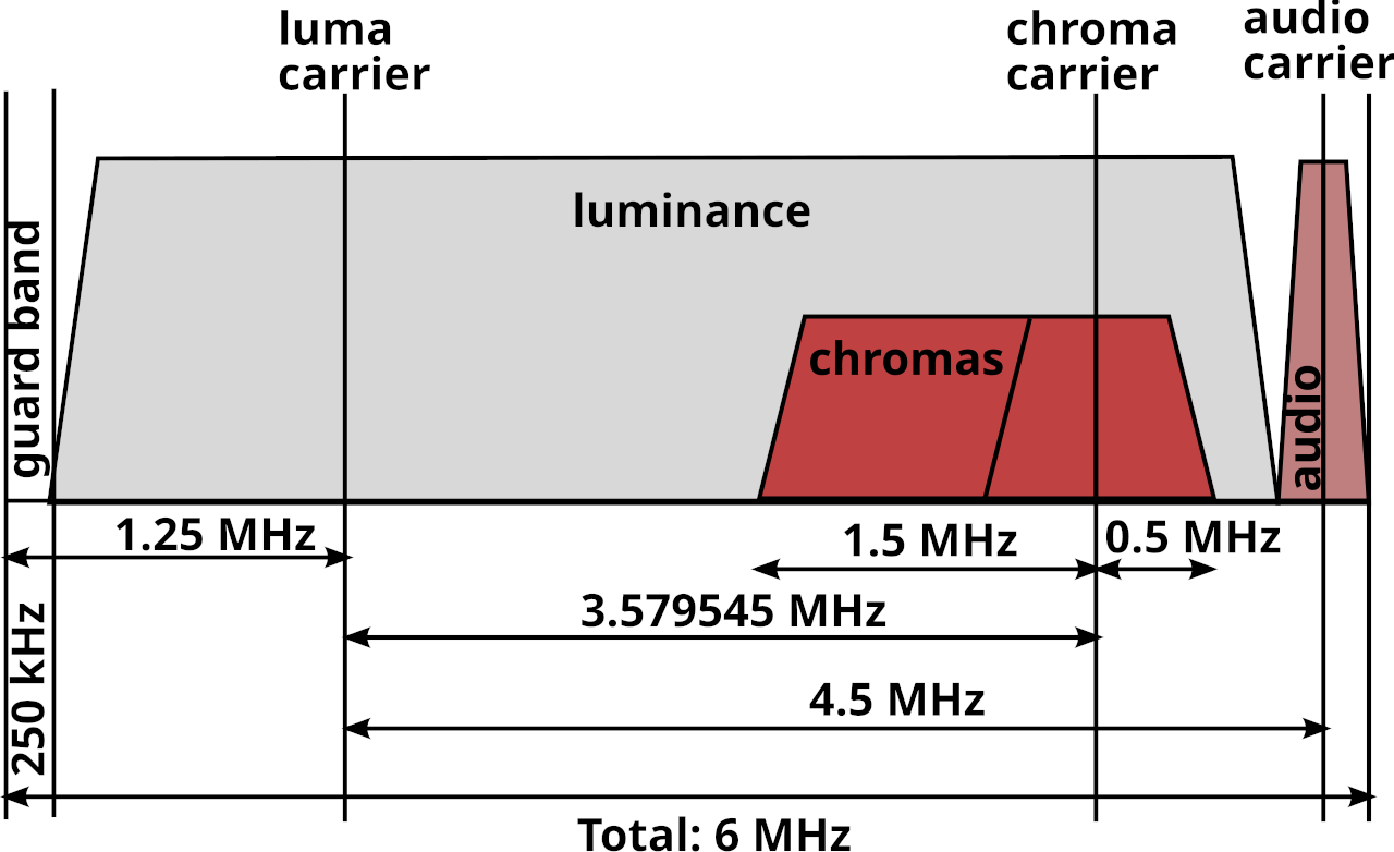
Composite video (the Yellow RCA connector on a console’s AV cable) is constructed by overlaying separate Luma (brightness) and Chroma (color) signals on top of each other so that only one wire (aside from ground) is needed to transmit the video.
This is typically done inside a game console, which makes Composite video one of the output options the console has.</p>

<p><img src="/assets/img/Ntsc_channel.png" alt="Composite encoding" /></p>

<p>
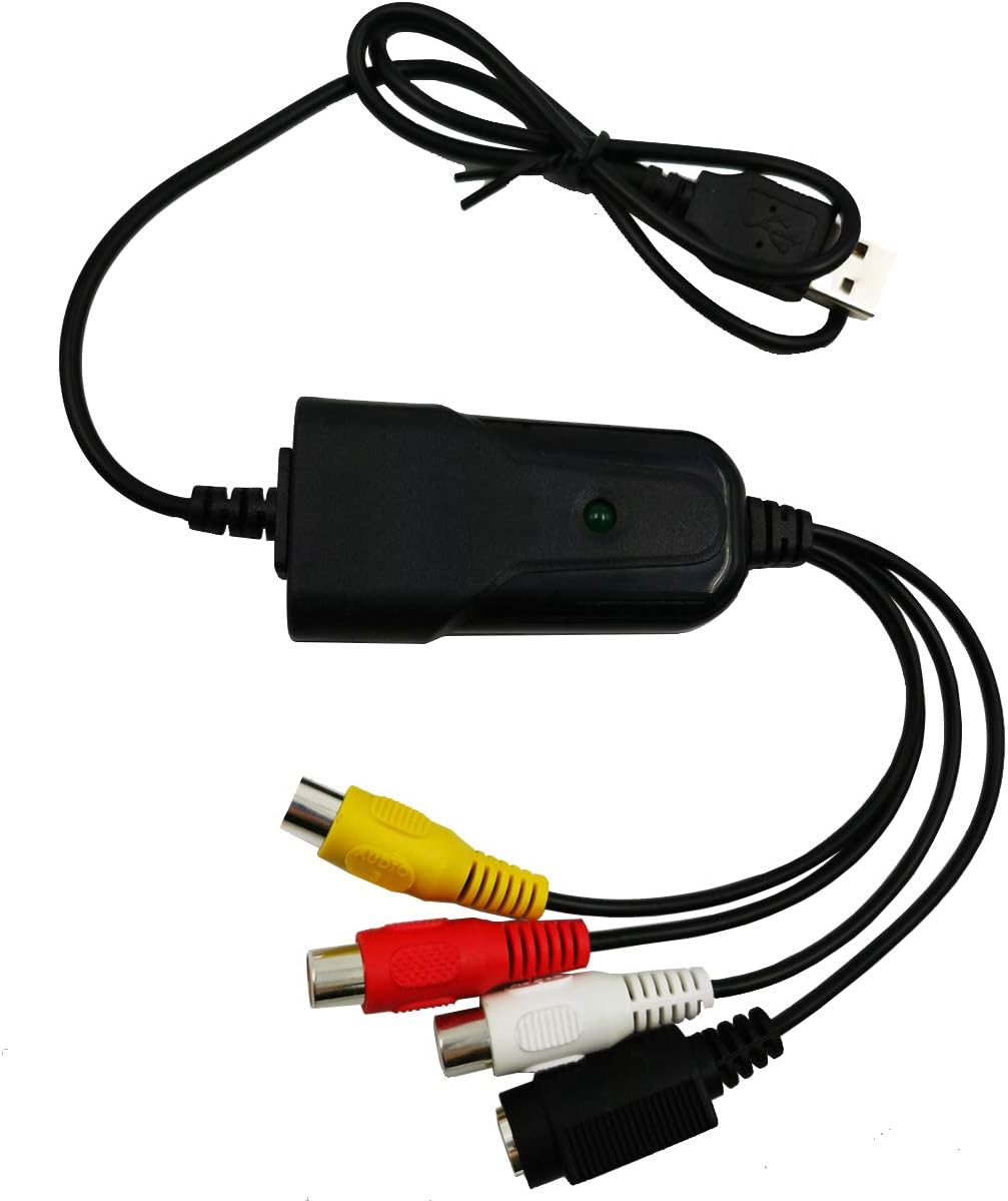
External Notch and Comb filters decode Composite video back into separate Luma and Chroma signals, typically known as S-Video.
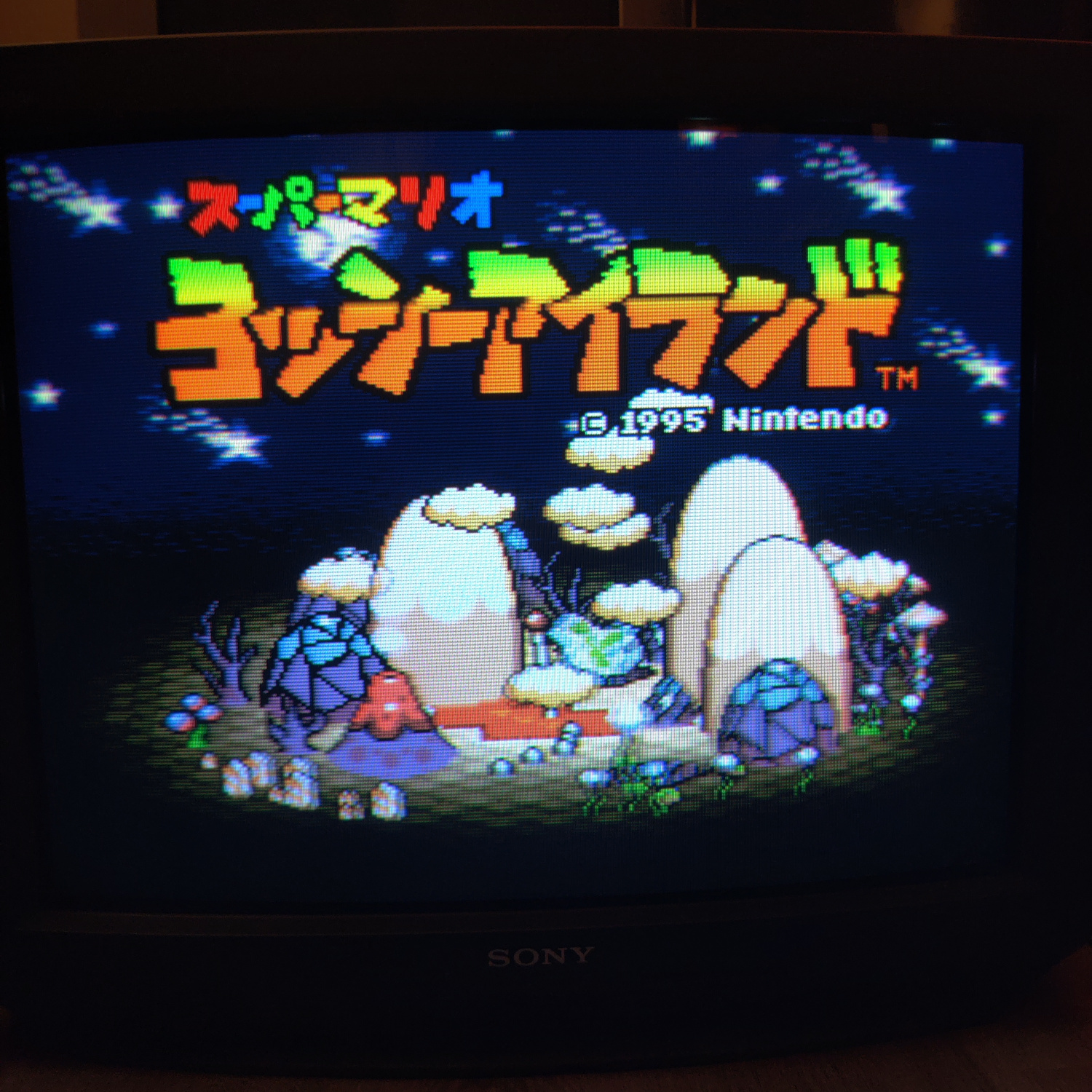
Inside any CRT there is going to be an internal filter that does this for you when you plug Composite video into it.
Using an external filter takes this job away from the TV and allows you to choose the means and quality of this conversion.</p>

<p><img src="/assets/img/ntscdb2fig2.png" alt="Composite decoding" /></p>

<p>
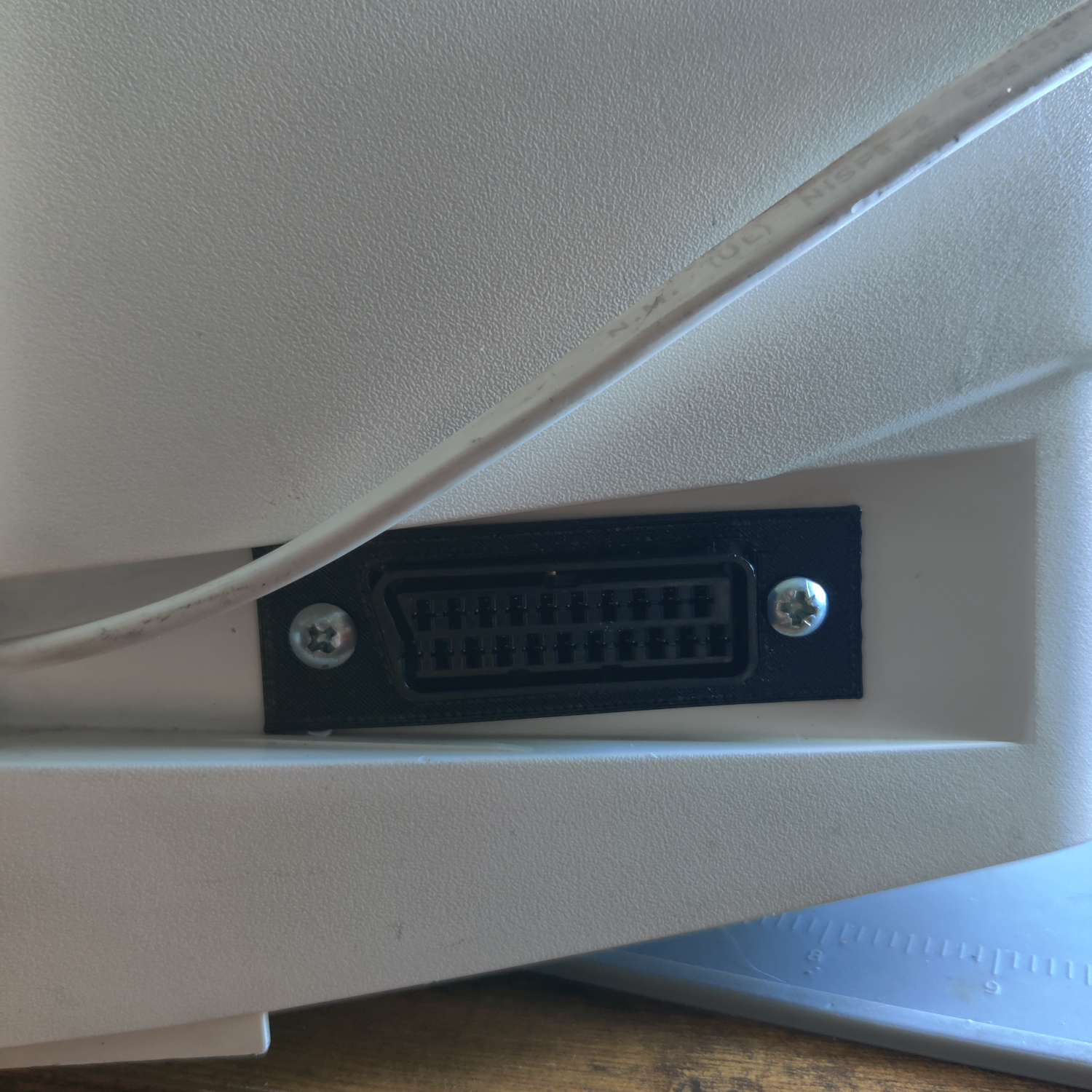
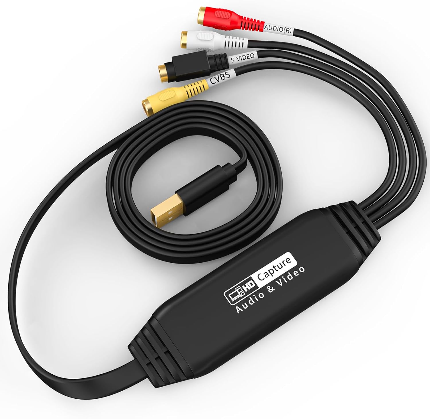
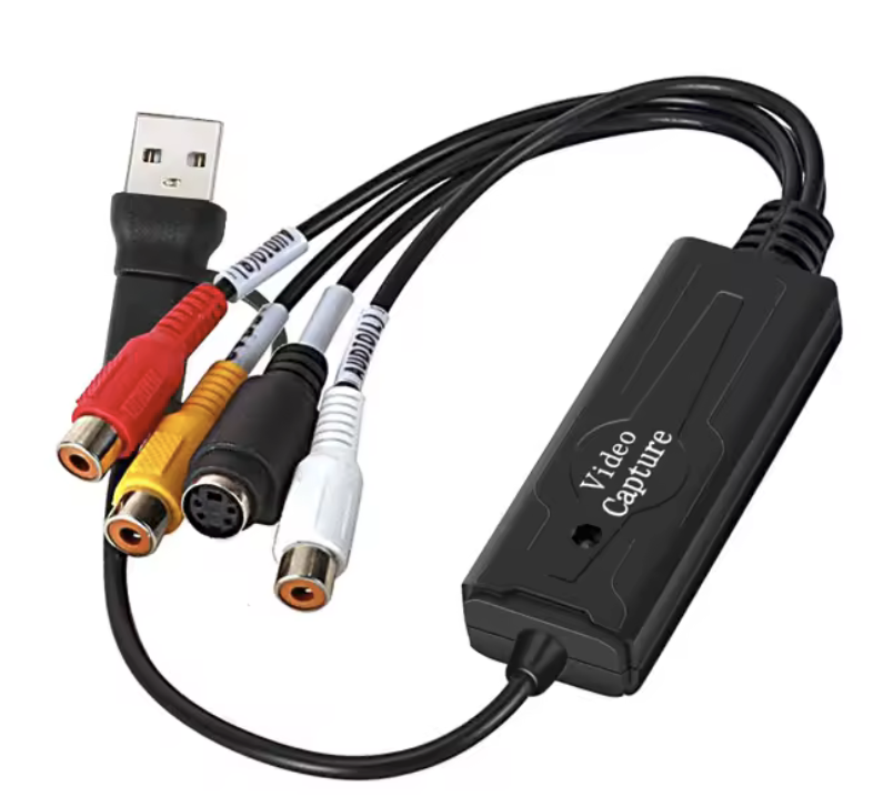
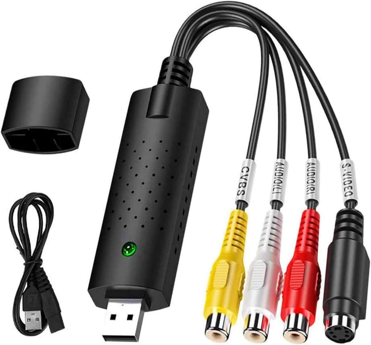
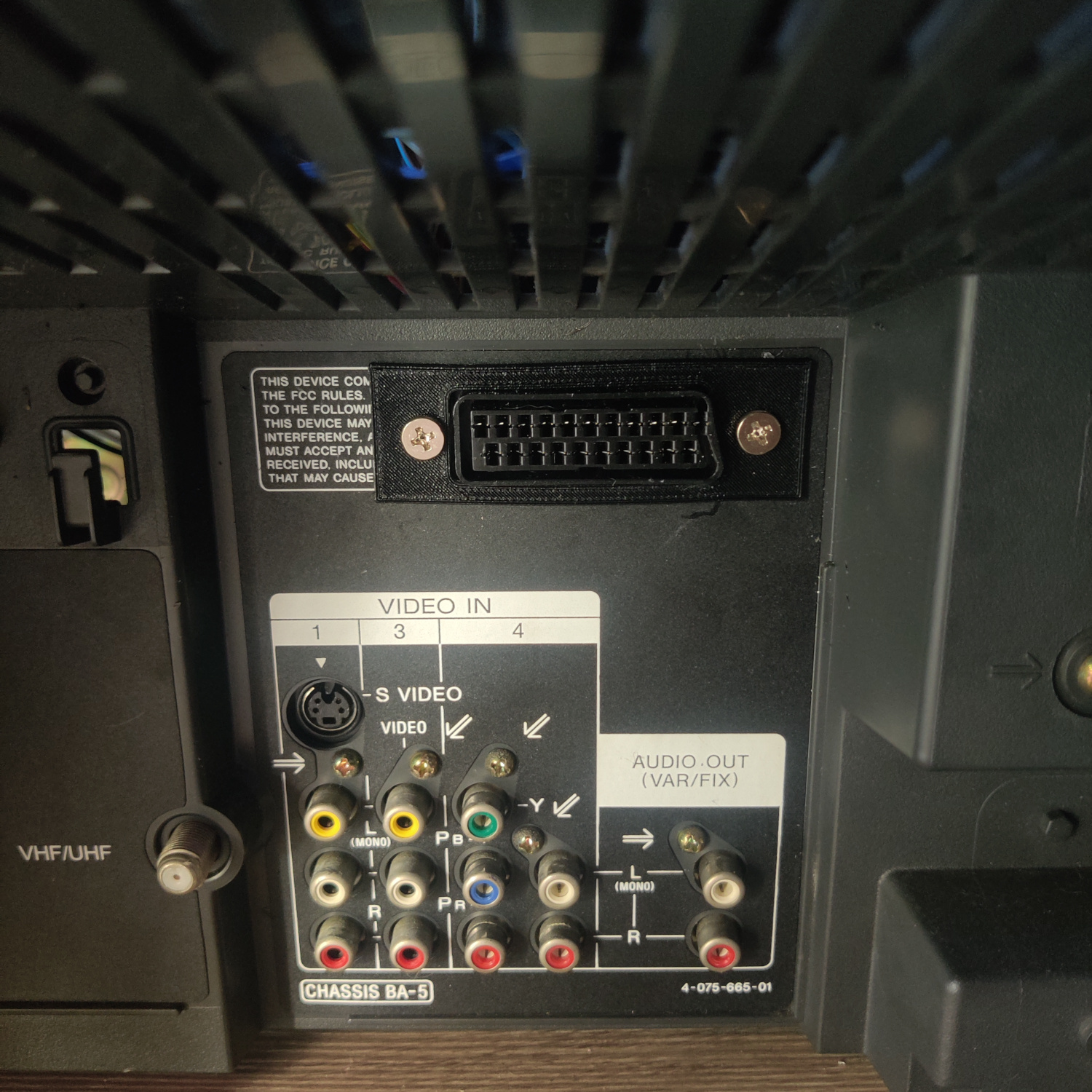
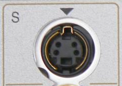
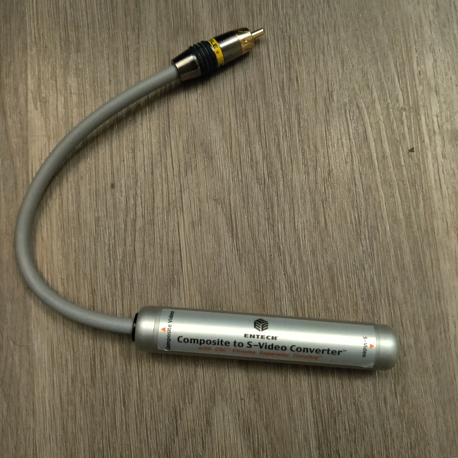
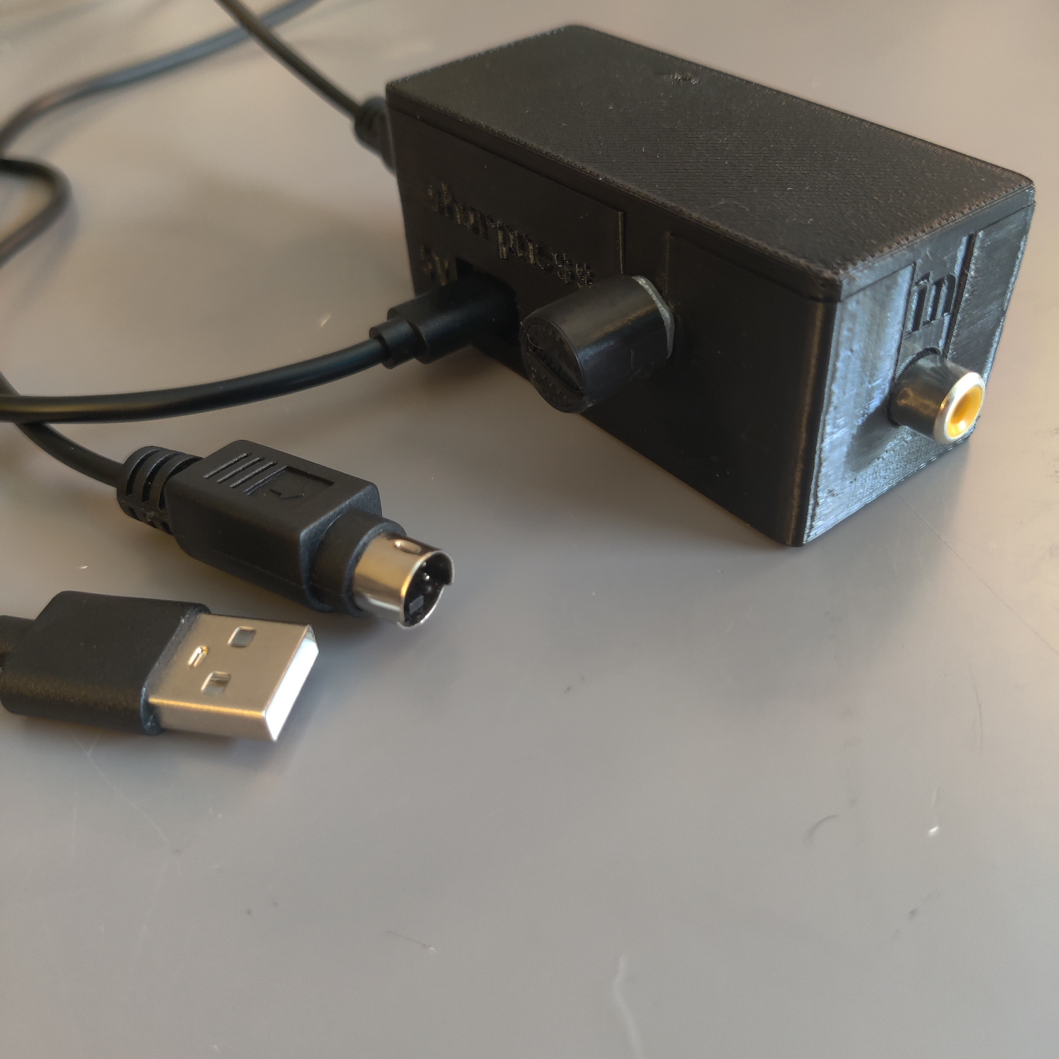
In order to use an external filter, the TV or Capture device you are connecting to needs to have S-Video input available. This is what that connector looks like:</p>

<p><img src="/assets/img/S.video.socket.png" alt="S-Video connector" /></p>

<h2 id="why-use-composite">Why Use Composite?</h2>

<p>A lot of people consider Composite video to be the worst option (aside from RF) when it comes to video output.
This is simply not true as Composite video offers some artistic benefits that other output options do not (including raw S-Video output from your console.)</p>

<p><a href="https://crtdatabase.com/articles/art-design">This Article by Eli Krause</a> goes into great detail on why Composite is the best video format for a lot of retro games, even into the PS1/Saturn/N64 era.
I highly recommend giving that article a read to better understand why Composite video is important.</p>

<p>
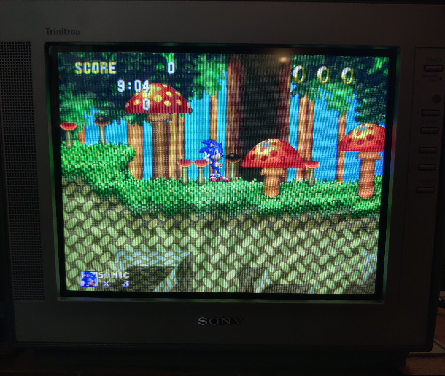
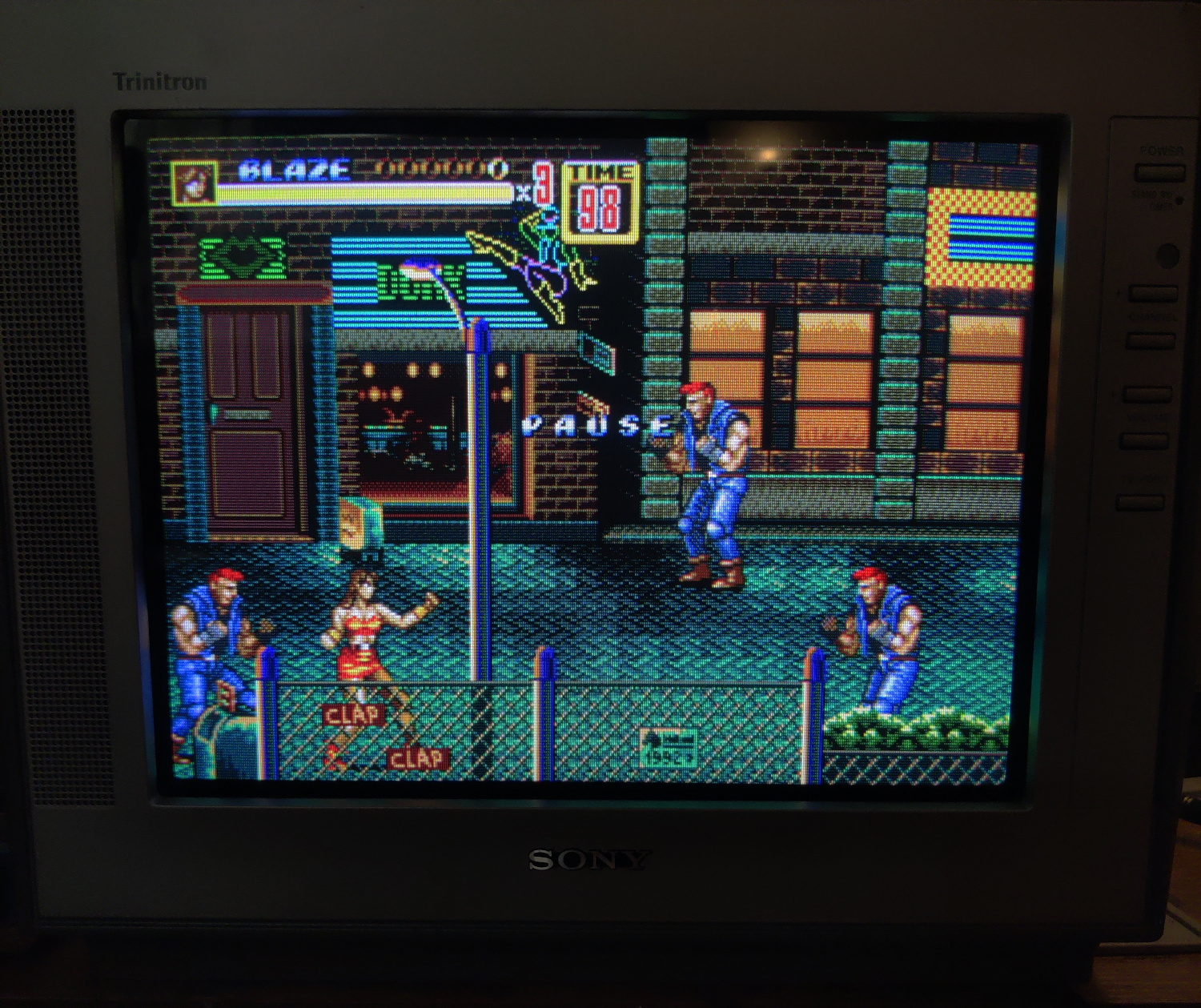
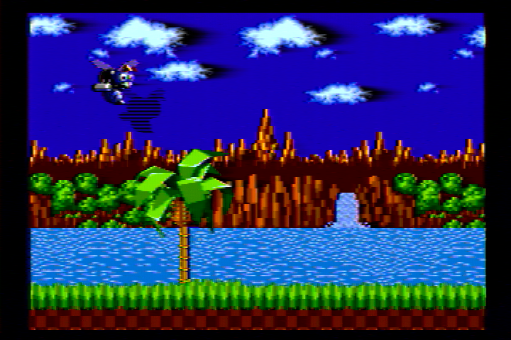
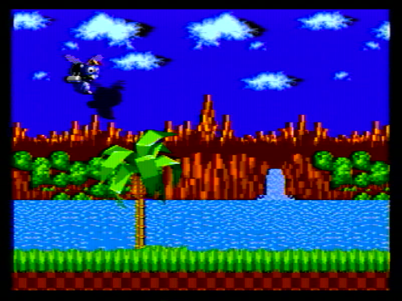
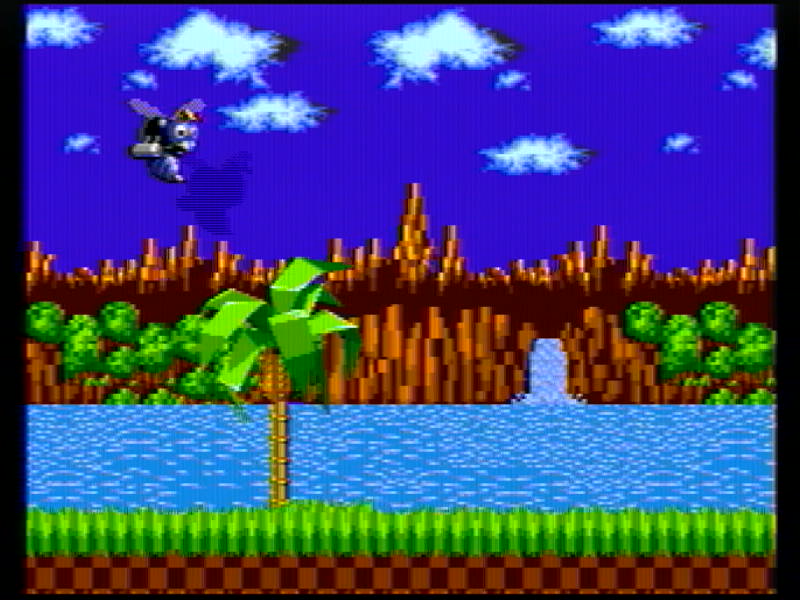
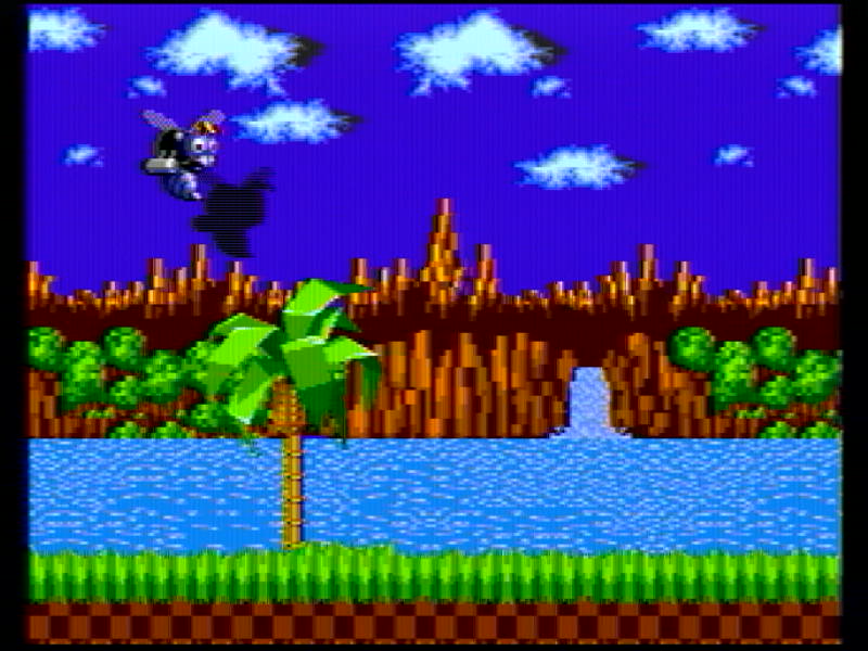
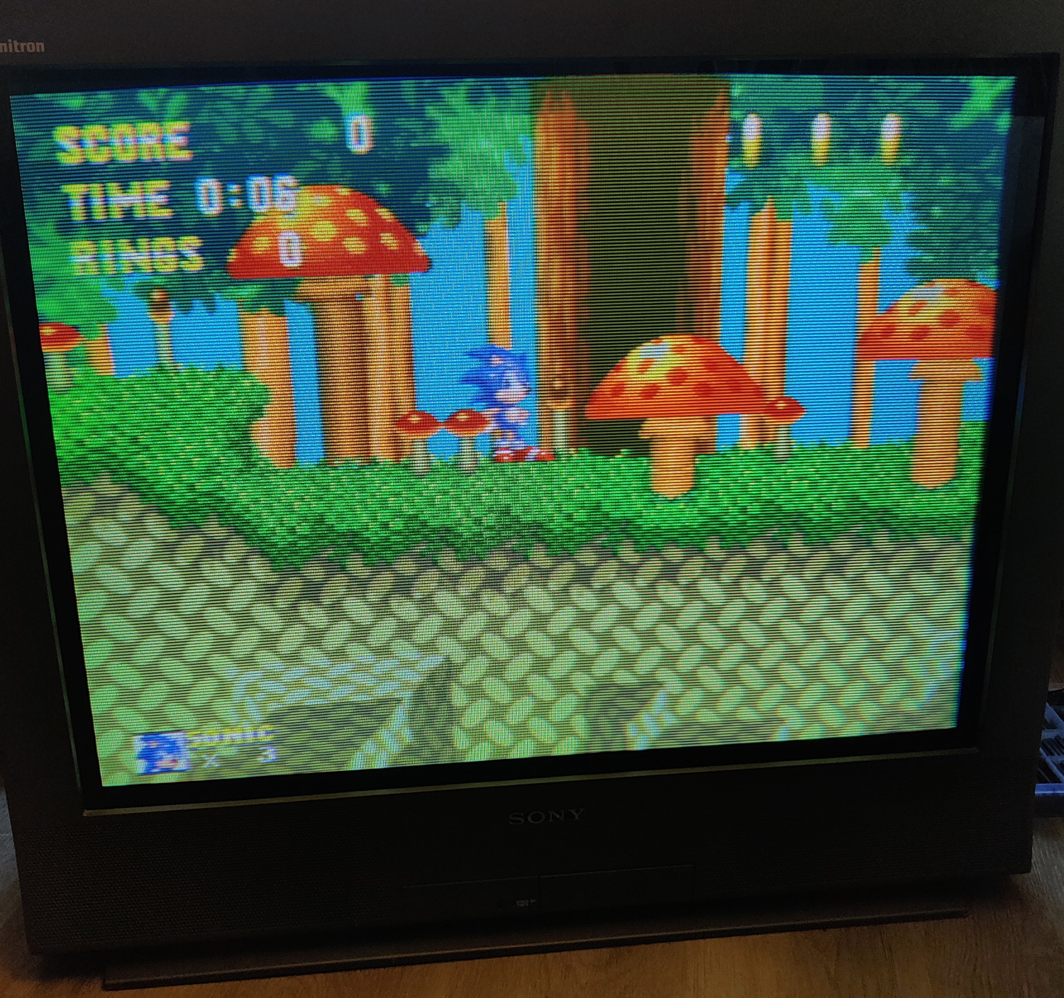
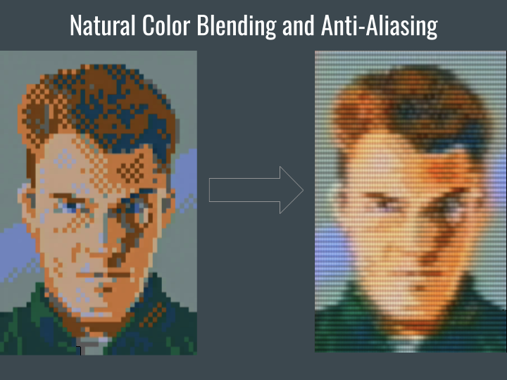
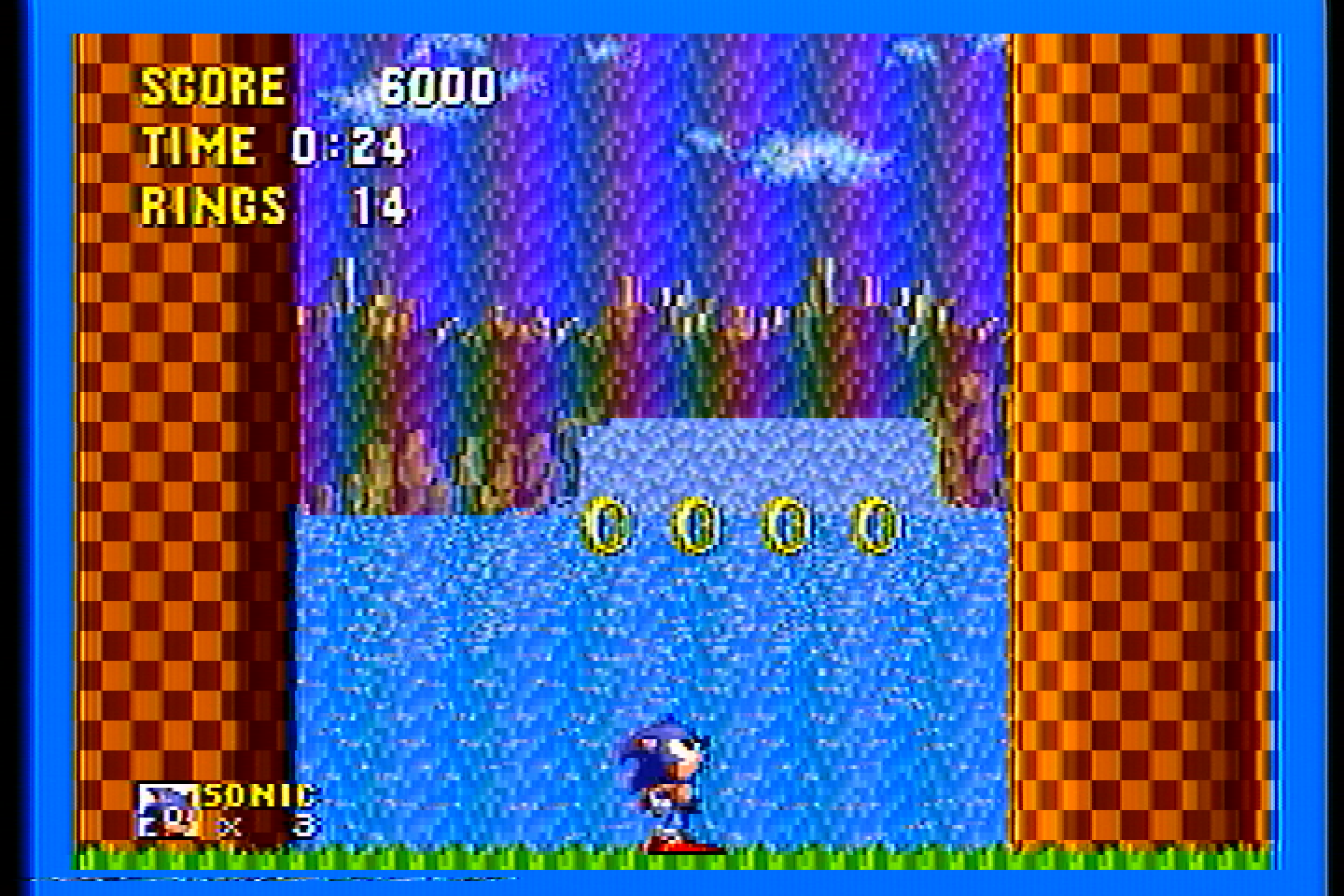
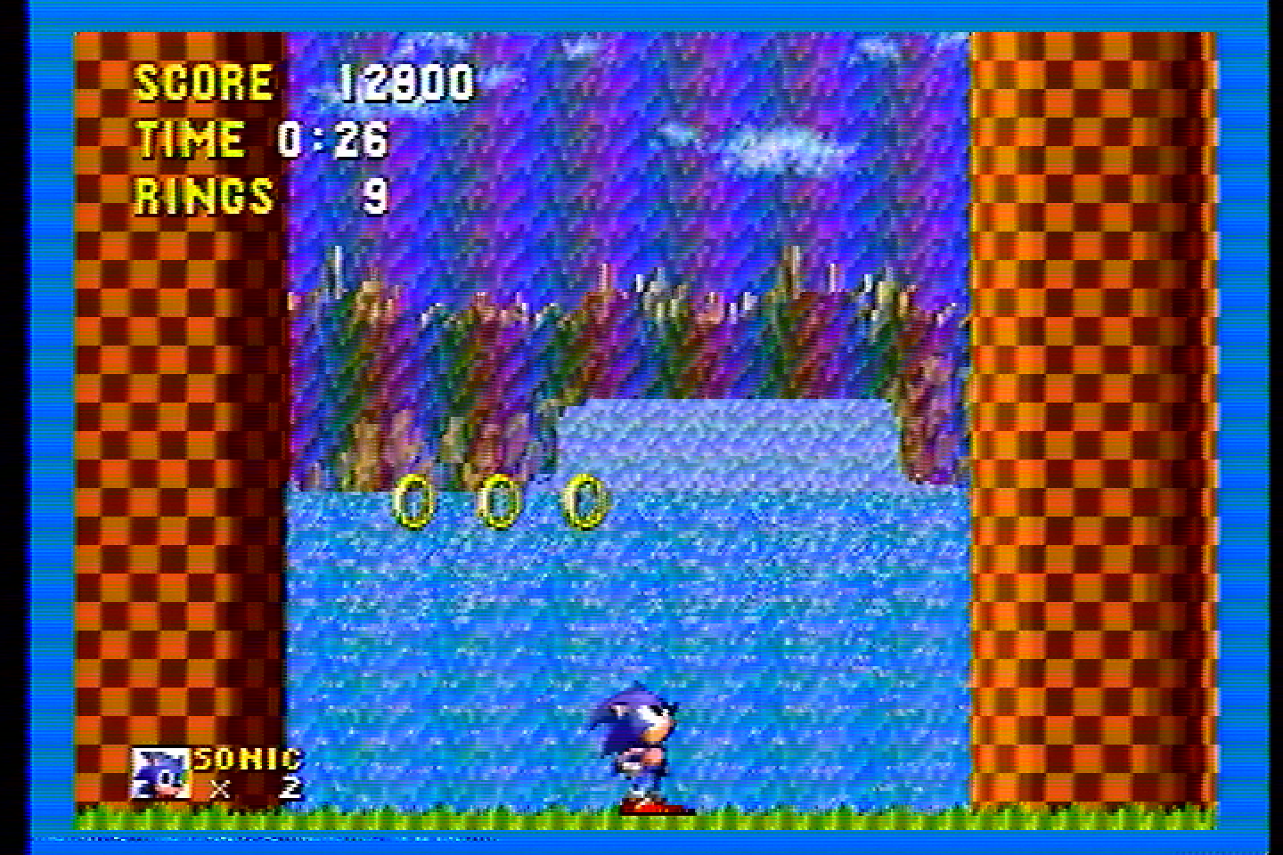
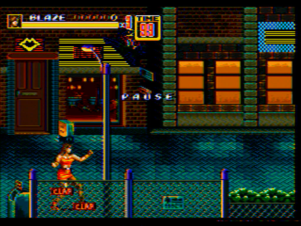
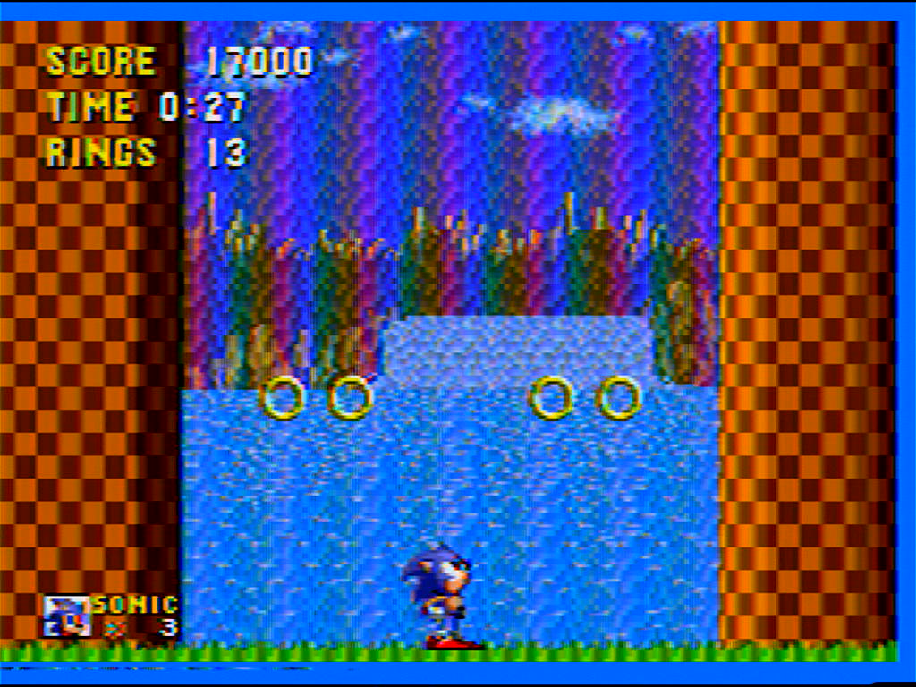
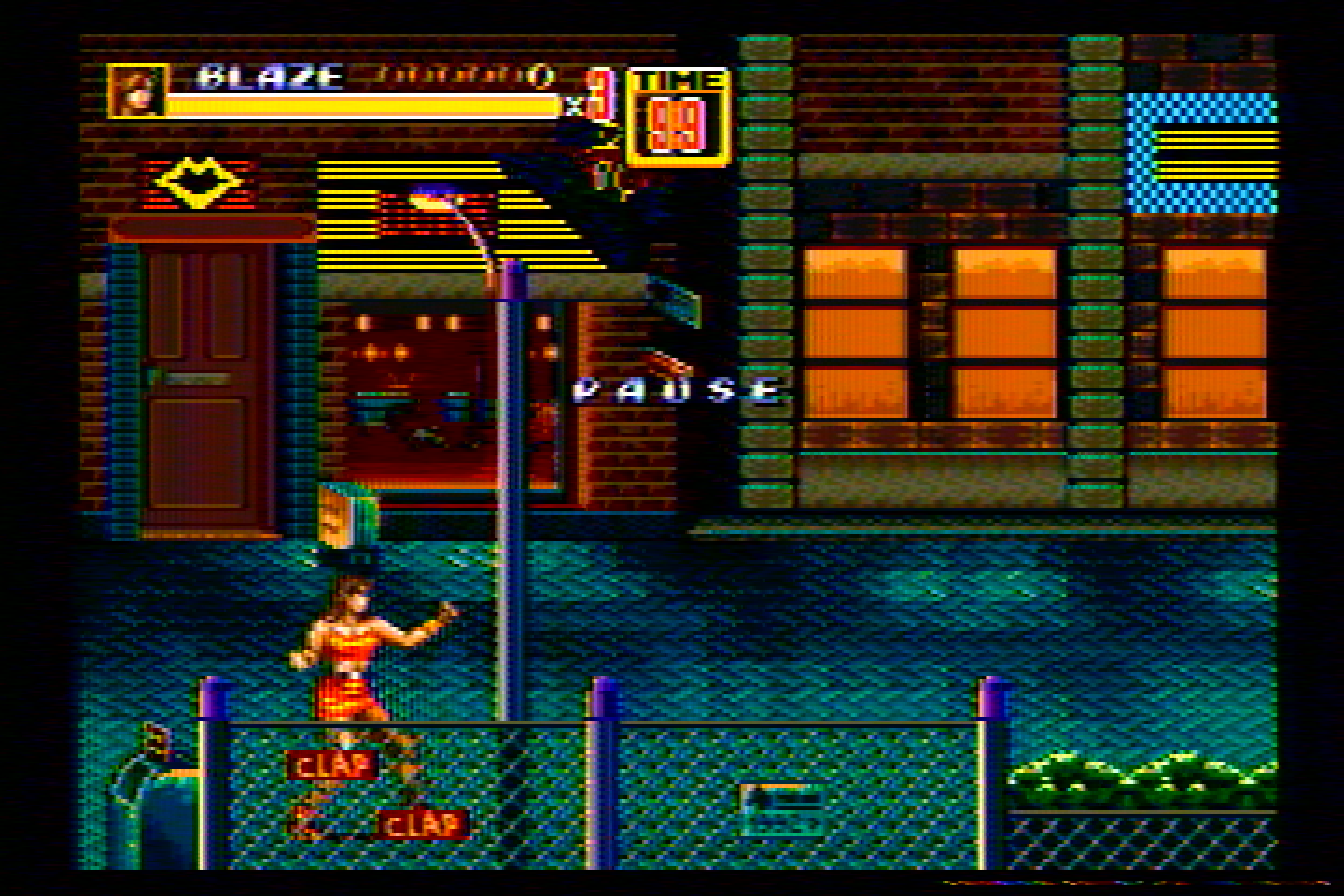
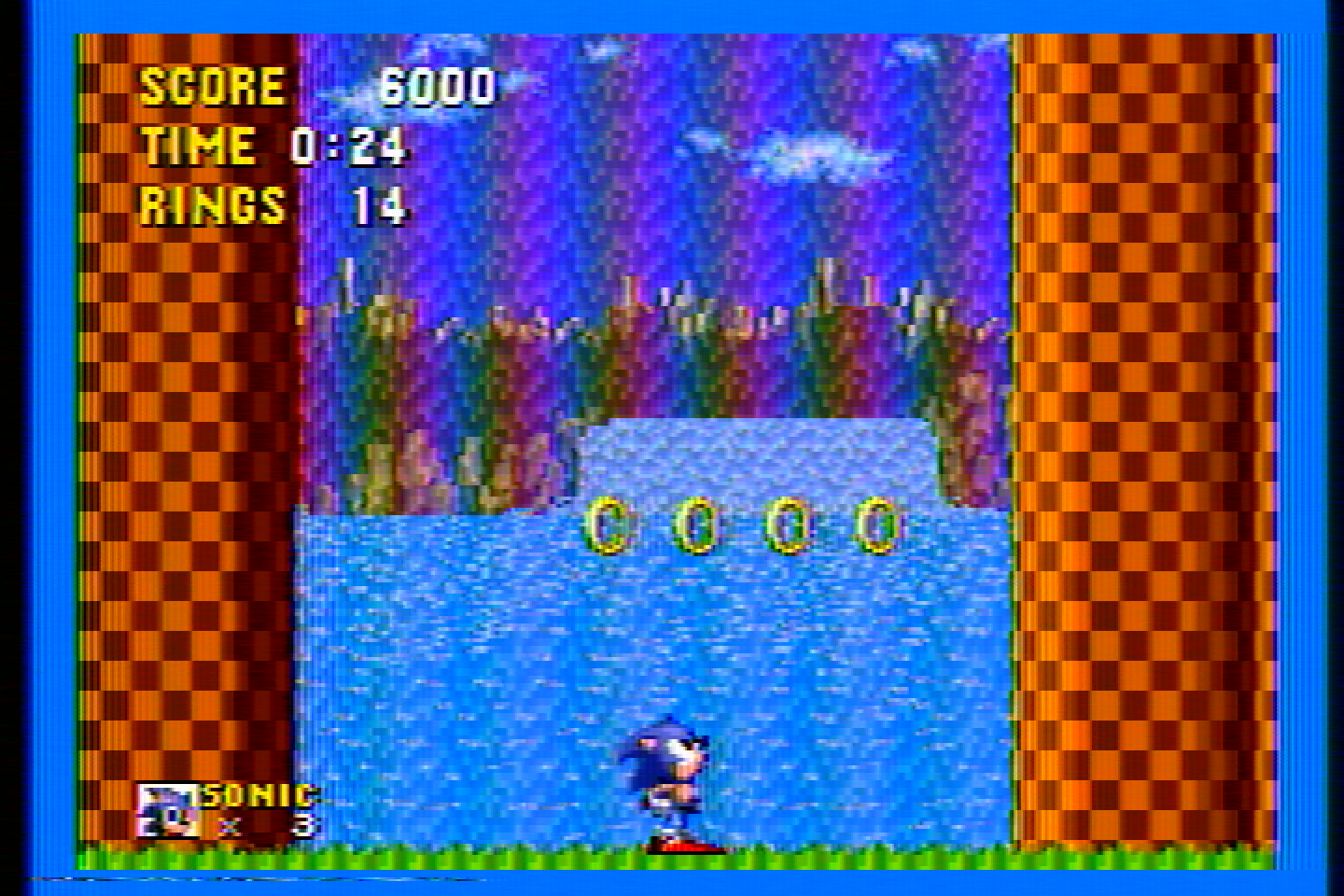
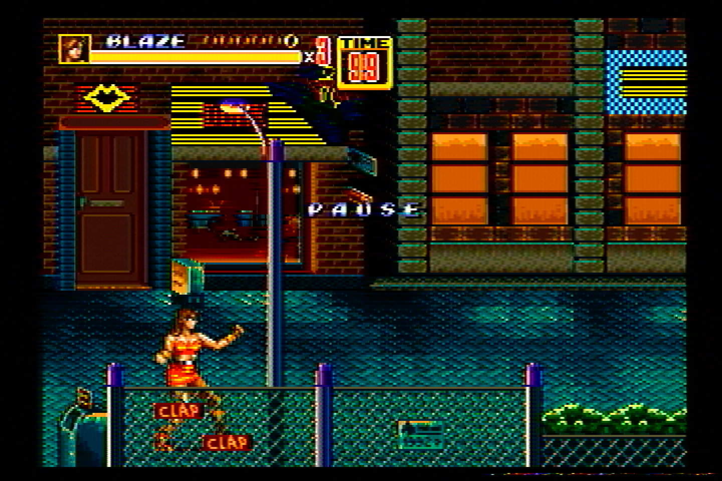
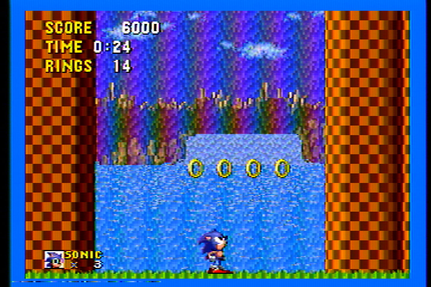
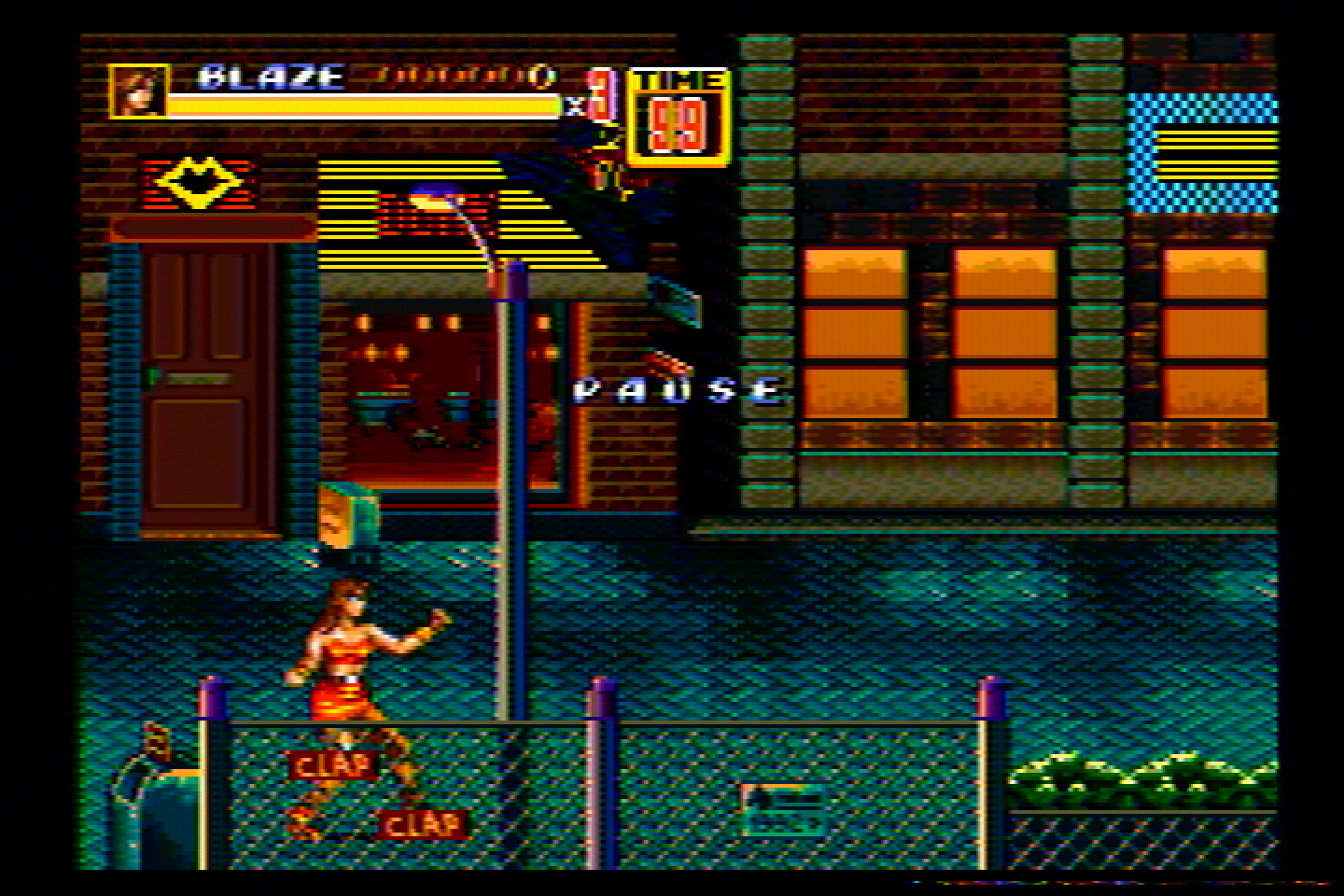
The TL;DR of that article is, Composite video allows for blending of colors that are especially important for dithering (Sonic Waterfall and Streets of Rage 2 lamp lighting are classic examples).
It also allows for a wider range of colors than the console could normally create by using two different colors next to each other that get blended into a new color.</p>

<p><img src="/assets/img/CRT%20Art.png" alt="Composite art example" /></p>

<h2 id="arent-comb-filters-the-best-option">Aren’t Comb Filters the Best Option?</h2>

<p>
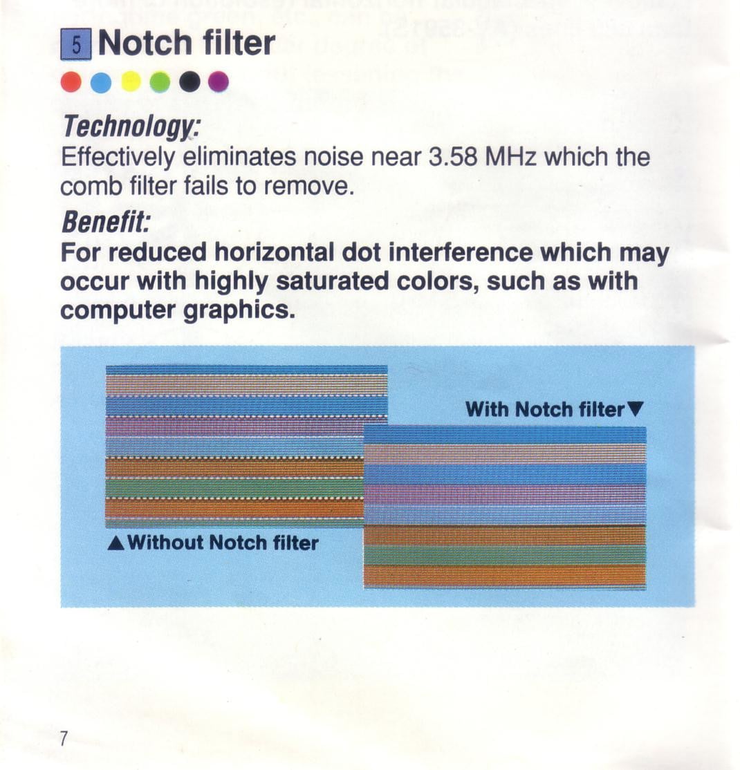
Comb filters are good for live video footage, but they are not good for retro gaming or computer visuals. Here’s a few info-graphics that will explain why:</p>

<p><img src="/assets/img/JVC%20Catalog%20Info.jpeg" alt="Notch and Comb comparison from JVC" /></p>

<p><img src="/assets/img/ExtronInfo.jpeg" alt="Extron Comb chroma mesh failure" /></p>

<p><img src="/assets/img/tinknote.jpeg" alt="Retro Tink on Notch" /></p>

<p>
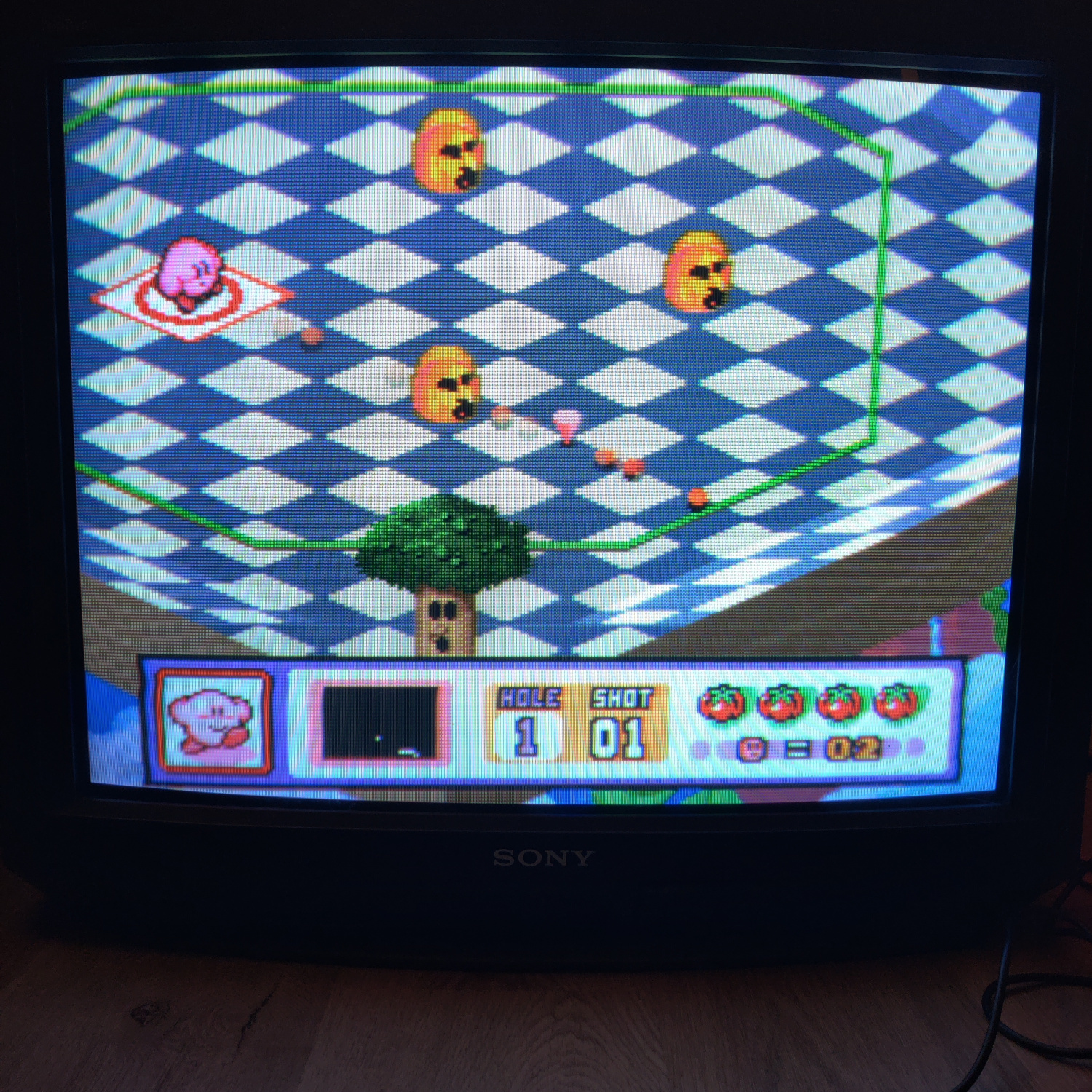
Here’s what that looks like in an actual game:</p>

<p><img src="/assets/img/Example%202.jpg" alt="Notch and Comb comparison" /></p>

<p>Notch filters do not exhibit this issue. This is often referred to as dot crawl, but the correct term is “hanging dots”.
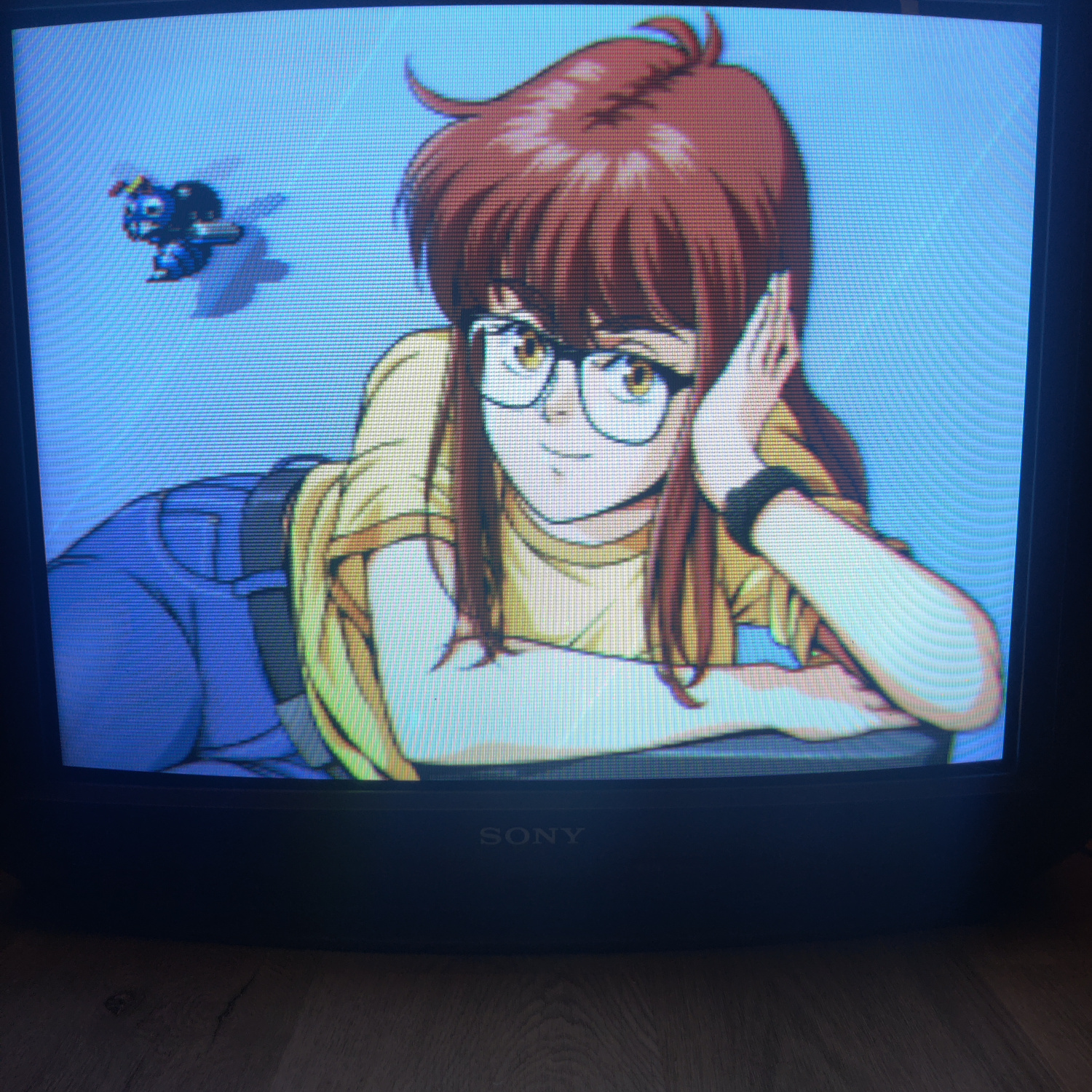
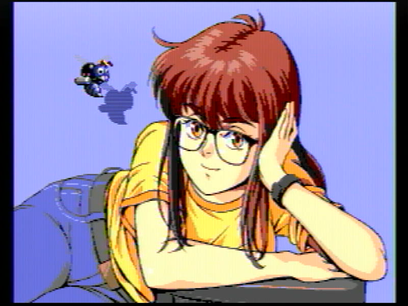
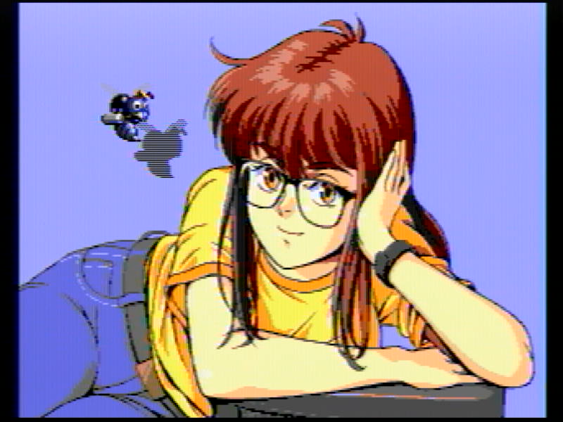
</p>

<p><a href="https://en.wikipedia.org/wiki/Dot_crawl">Dot crawl</a> is an artifact of the Luma information being polluted by the Chroma signal, which looks like this:</p>

<p><img src="/assets/img/Crawl.jpg" alt="dot crawl" /></p>

<p>
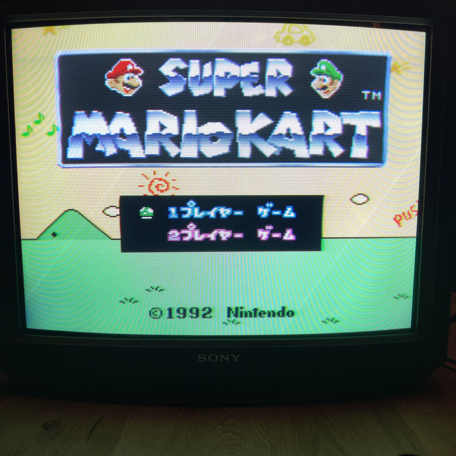
Another type of interference you will see is called “rainbowing” or “rainbow banding”, which results from the Chroma information being polluted by the Luma signal.</p>

<p><img src="/assets/img/Kramer%2008.png" alt="rainbow artifacts" /></p>

<p><em><strong>NOTE</strong>: The amount of rainbow artifacts and dot crawl are also dependant on the console itself. A lot of stock Genesis consoles have bad rainbowing, but modding them can improve or eliminate it. 
The Wii has very good composite output, for example. How the picture looks depends on the encoding <strong>AND</strong> the decoding.</em></p>

<p>Both Comb filters and Notch filters will exhibit dot crawl and rainbow artifacts to varying degrees, this is the nature of Composite video.
The only way to not have these artifacts is to keep Chroma and Luma separate from the very beginning, but you then lose some of the artistic qualities that Composite offers.</p>

<p>The goal, then, is to use a filter that minimizes dot crawl and rainbow artifacts, and does not have hanging dots. This can only be done with a Notch filter, as you’ll see.</p>

<h2 id="comb-filter-comparisons">Comb Filter Comparisons</h2>

<p>
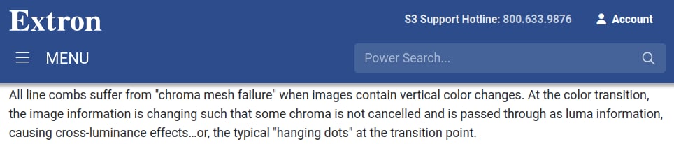
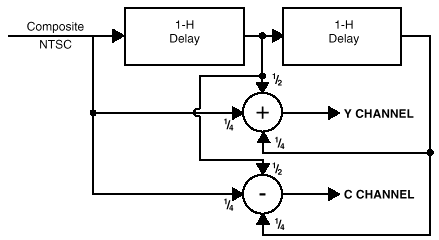
Comb filters work by splitting the Composite signal into Luma(Y) and Chroma (C) signals using delay lines and adding and subtracting multiple lines of video to extract the Y and C information. They are much more complex than notch filters, if you want to know more about how they work, check out <a href="https://www.extron.com/article/ntscdb3">this article by Extron</a>.</p>

<p><img src="/assets/img/comb_filter_diagram.png" alt="comb filter diagram" /></p>

<p>I purchased two different external comb filters to compare them to each other, and to the Notch filters later in this article.</p>

<p>
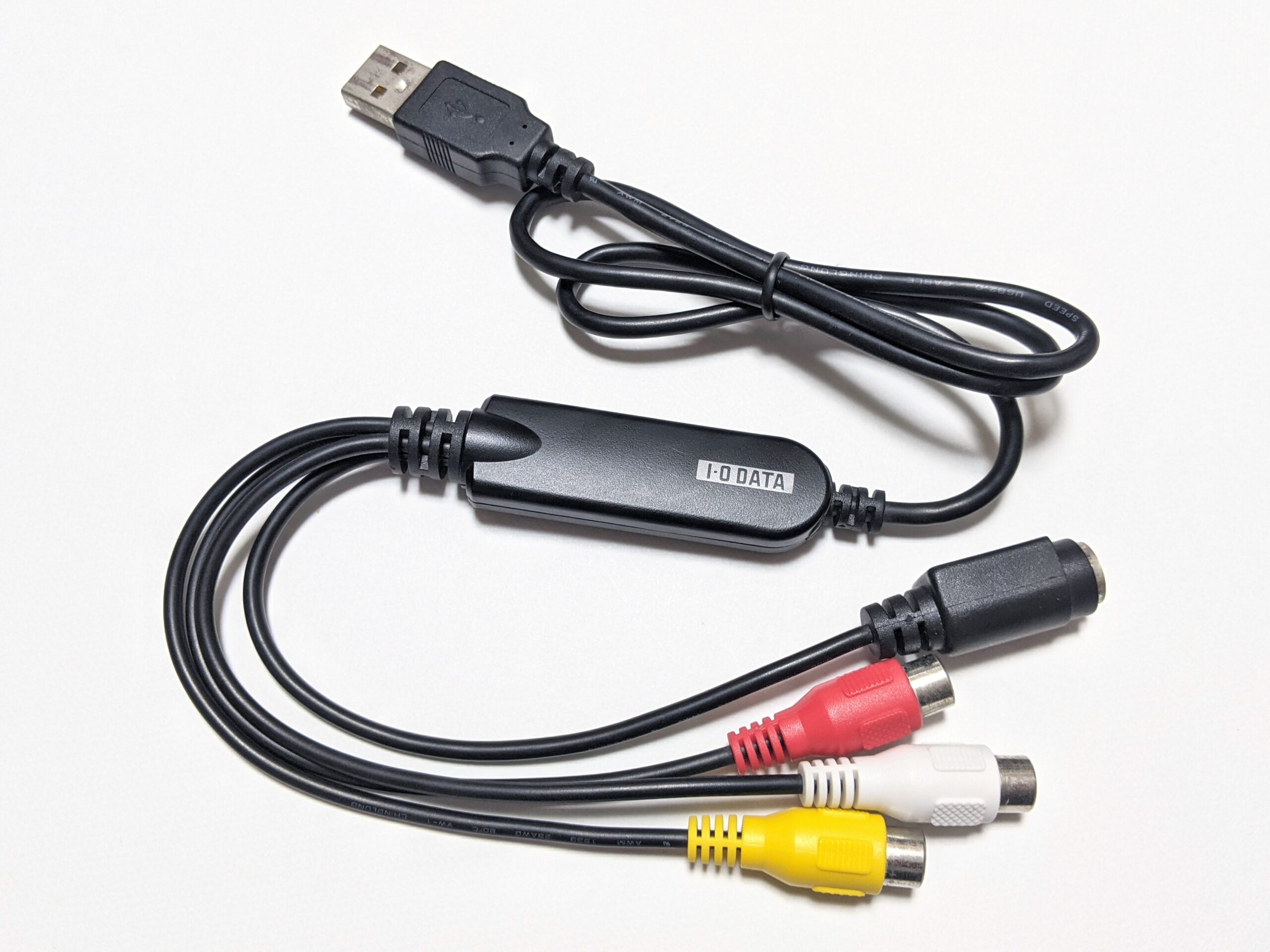
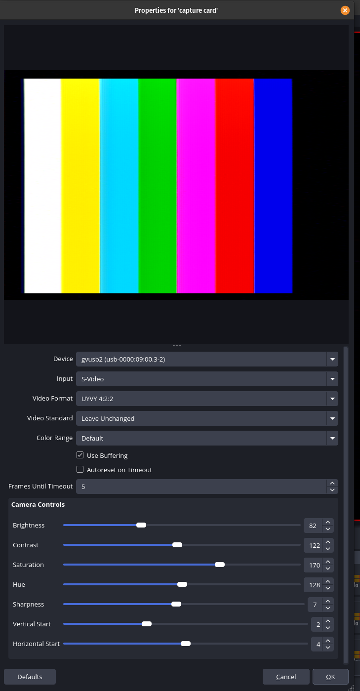
All comparisons were done using an I-O DATA GV-USB2 S-Video capture device or an HDMI capture device with a VGA to HDMI adapter, and the following consoles’ composite output:</p>

<ul>
  <li>Sega Genesis Model 1 VA 6.5, recapped with no mods</li>
  <li>NES-001 Front Loader, recapped and modded with Lava RGB v1</li>
  <li>SNES SHVC-CPU-01, recapped with no mods</li>
  <li>N64 NUS-CPU-04, recapped with no mods</li>
</ul>

<p>
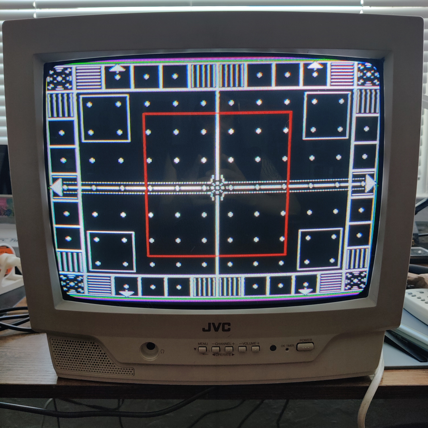
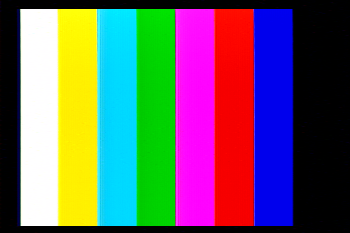
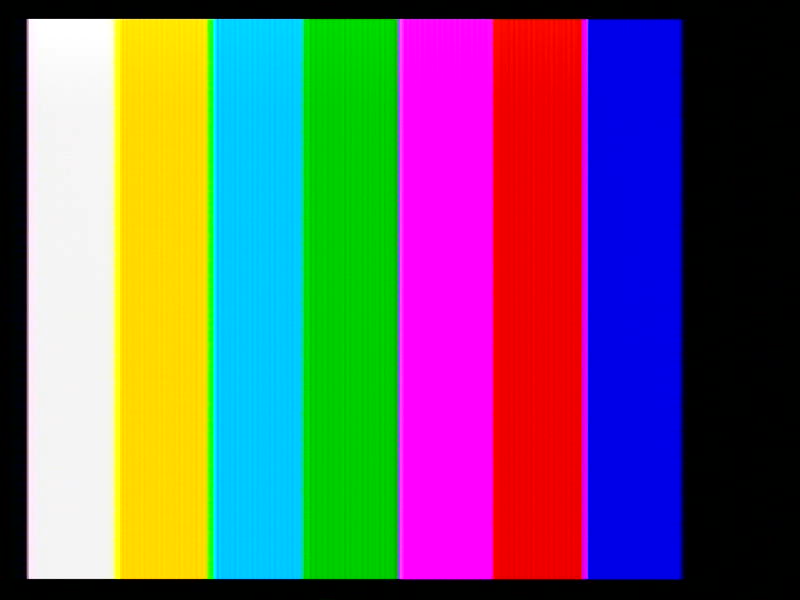
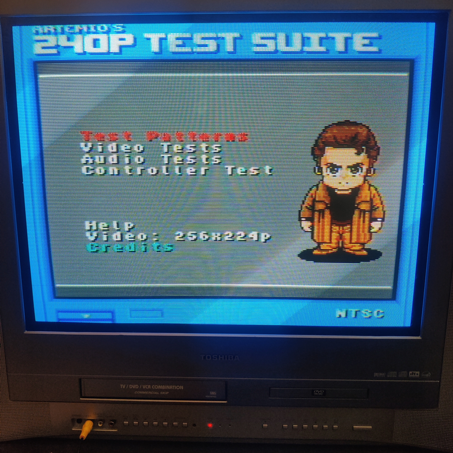
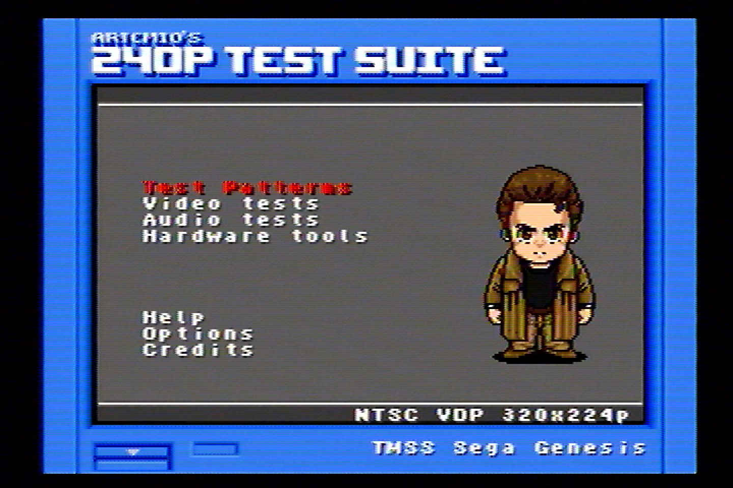
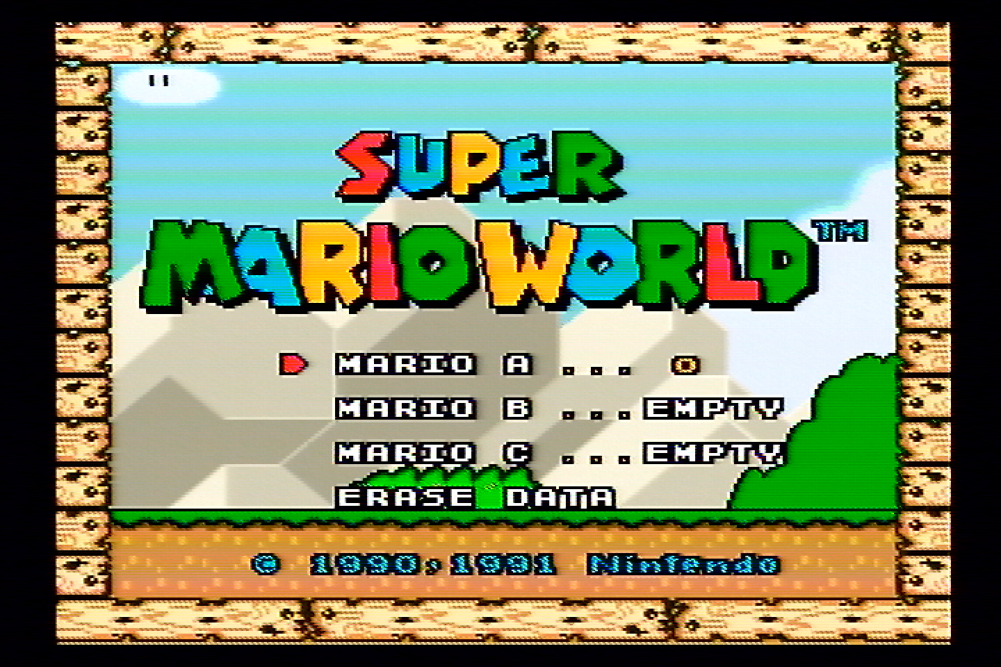
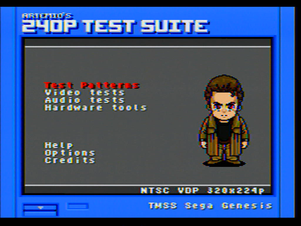
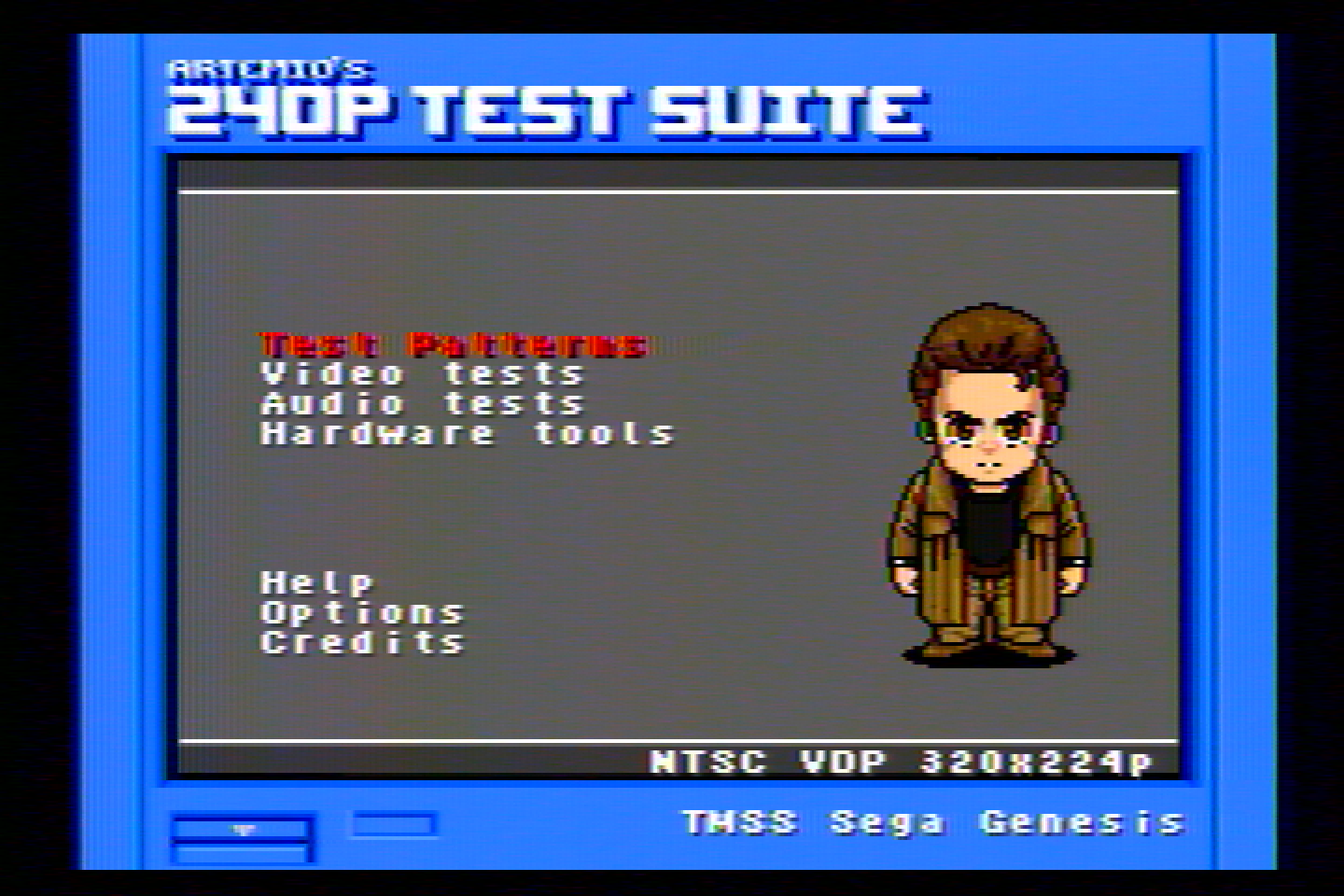
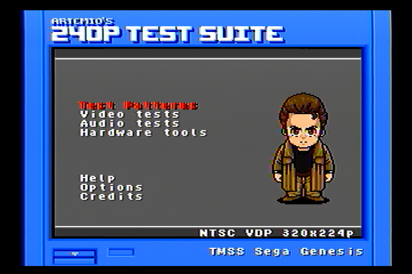
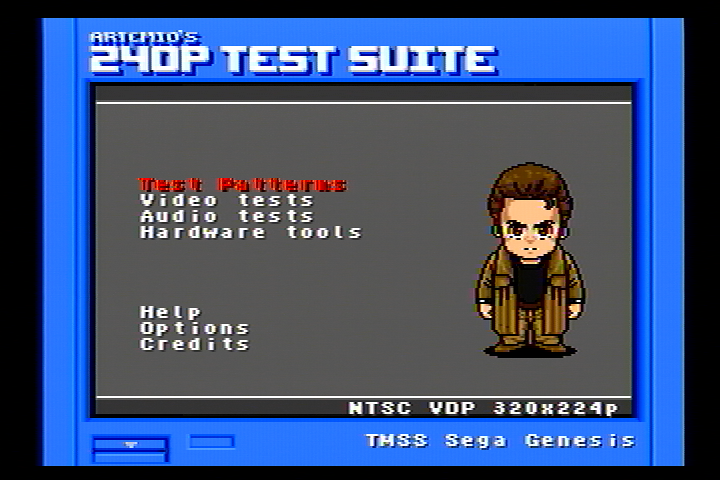
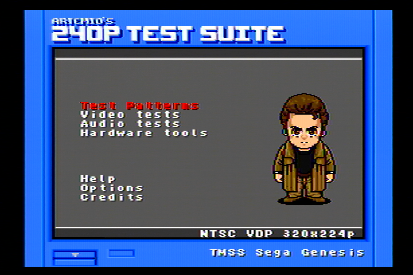
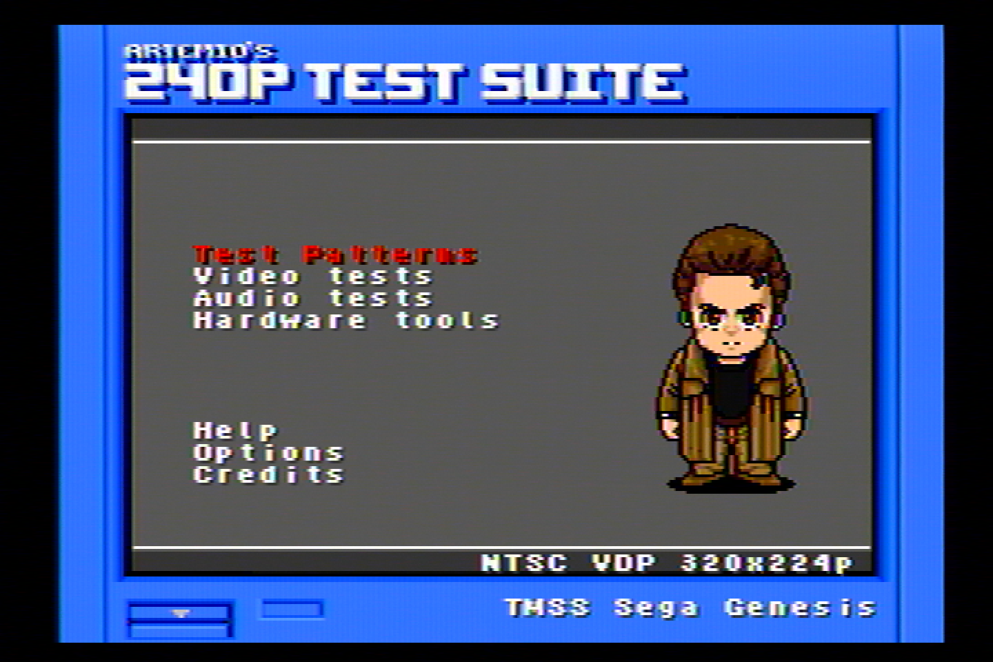
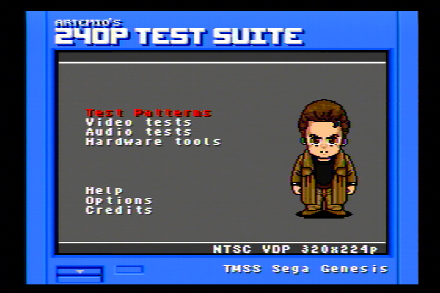
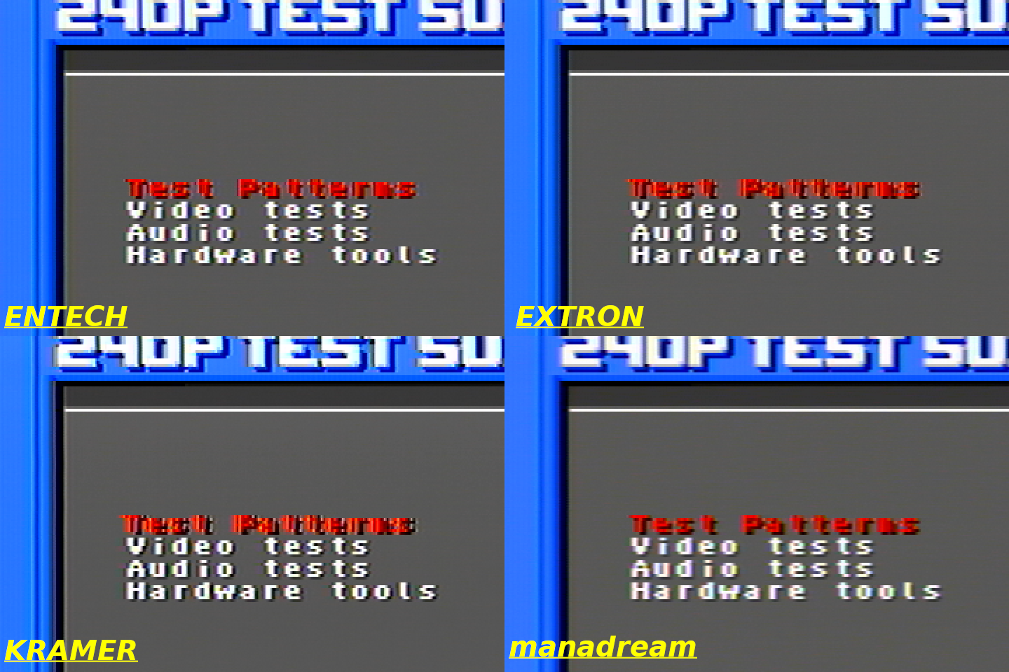
All 240p Test Suite images are from the Sega Genesis. This console has some jailbars and pretty bad rainbowing, so the video isn’t the best, but I think it is a good test because it shows how well different filters handle the imperfect video, plus this is what most stock Genesis consoles are going to look like.</p>

<h3 id="extron-ycs-sw6-three-line-comb-filter">
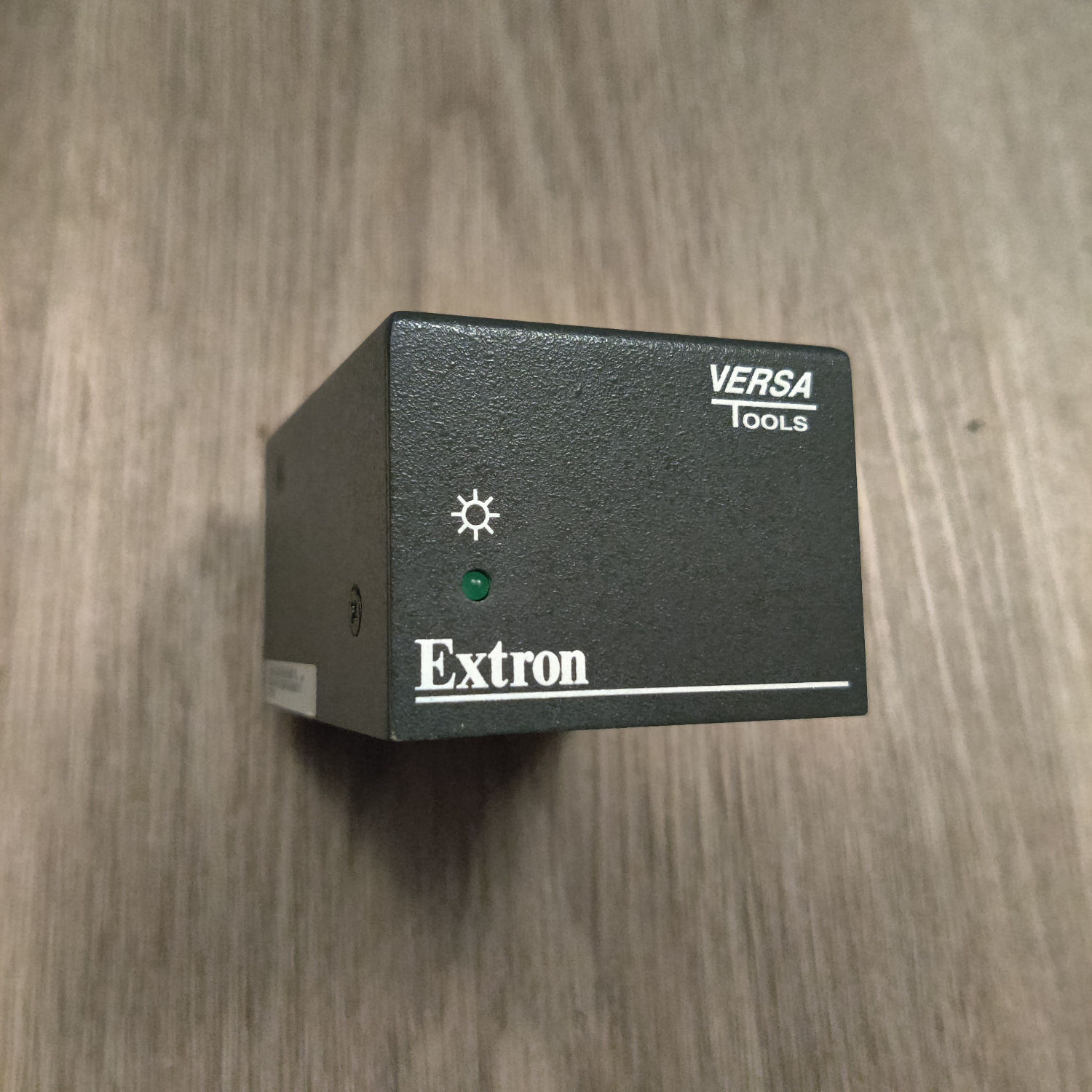
Extron YCS SW6 (Three-Line Comb Filter)</h3>

<p><img src="/assets/img/ycssw6mx-lg.jpg" alt="YCS SW6" /></p>

<p>
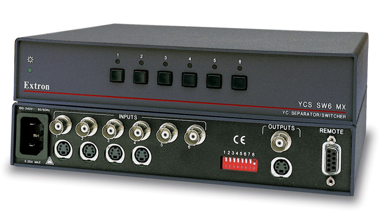
I bought this on Ebay for $34. You may be asking, why buy a video switcher for this test? Well this particular video switcher has a built-in 3-line comb filter made by Extron. So it can switch between video sources and also convert them to S-Video using the built in comb filter. It has 6 composite BNC inputs and can output composite, or S-Video using the comb filter (which is what I used).</p>

<p><img src="/assets/img/ExtronYCSSW6%2007.png" alt="240p Menu" />
<img src="/assets/img/ExtronYCSSW6%2006.png" alt="SMTP Color Bars" />
<img src="/assets/img/ExtronYCSSW6%2005.png" alt="240p Girl" />
<img src="/assets/img/ExtronYCSSW6%2004.png" alt="SoR2" />
<img src="/assets/img/ExtronYCSSW6%2008.png" alt="Sonic" />
<img src="/assets/img/ExtronYCSSW6%2003.png" alt="Mario 64" />
<img src="/assets/img/ExtronYCSSW6%2002.png" alt="SMW" />
<img src="/assets/img/ExtronYCSSW6%2001.png" alt="Duck Tales" /></p>

<p>For whatever reason, this filter had a lot of noise in the Chroma signal, which you can see as horizontal sections looking off-color. I did what I could to reduce noise as much as possible, but this unit might have something wrong with it.</p>

<p>
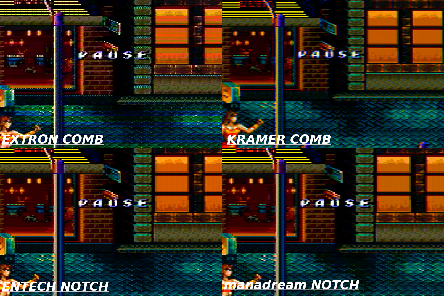
If you ignore that oddity, you can see the kinds of horizontal dot artifacts combs have, hanging dots, very clearly in:</p>

<ul>
  <li>The Streets of Rage 2 screenshot along the top of the fence and the bottom of the windows and the top of the bricks.</li>
  <li>
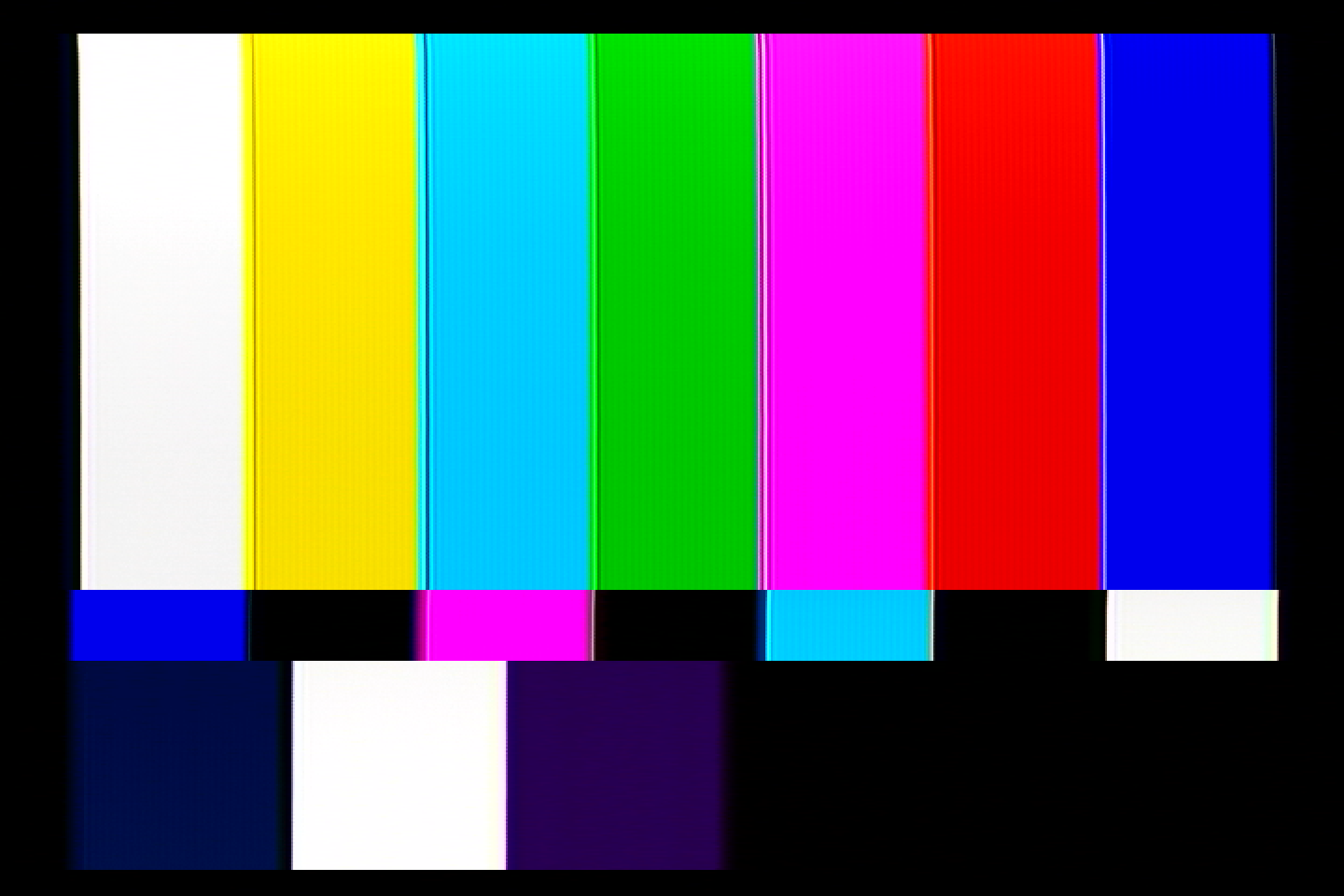
The top and bottom of the red letters in the 240p test suite.</li>
  <li>
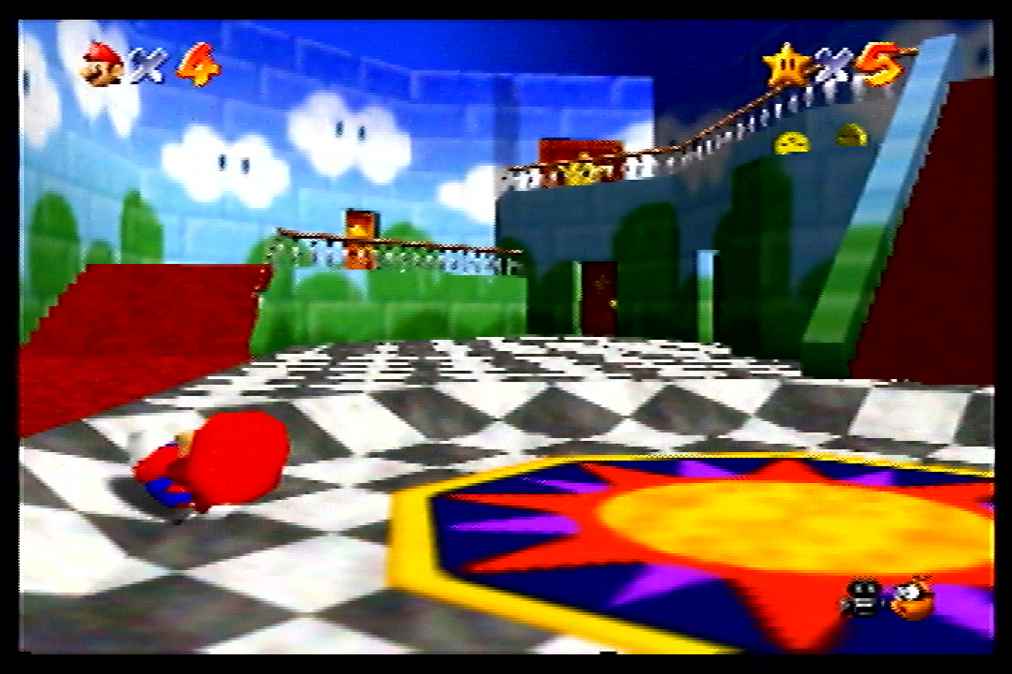
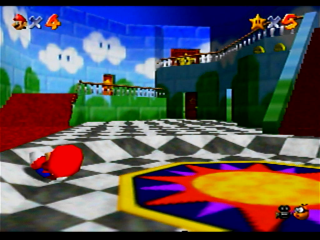
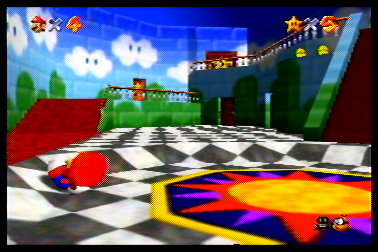
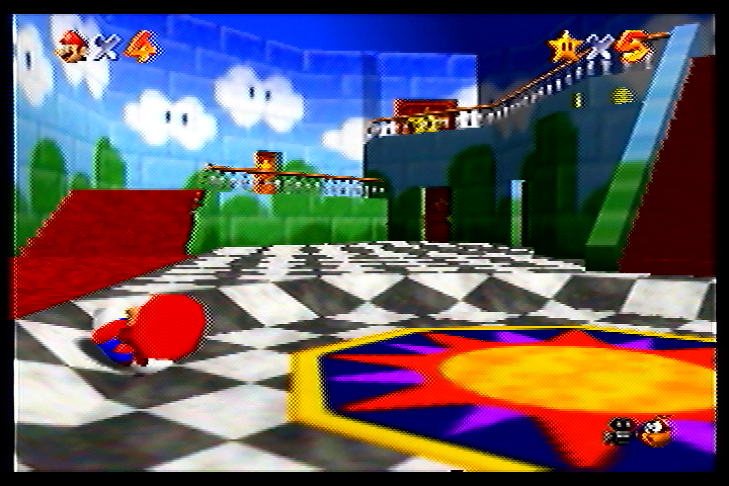
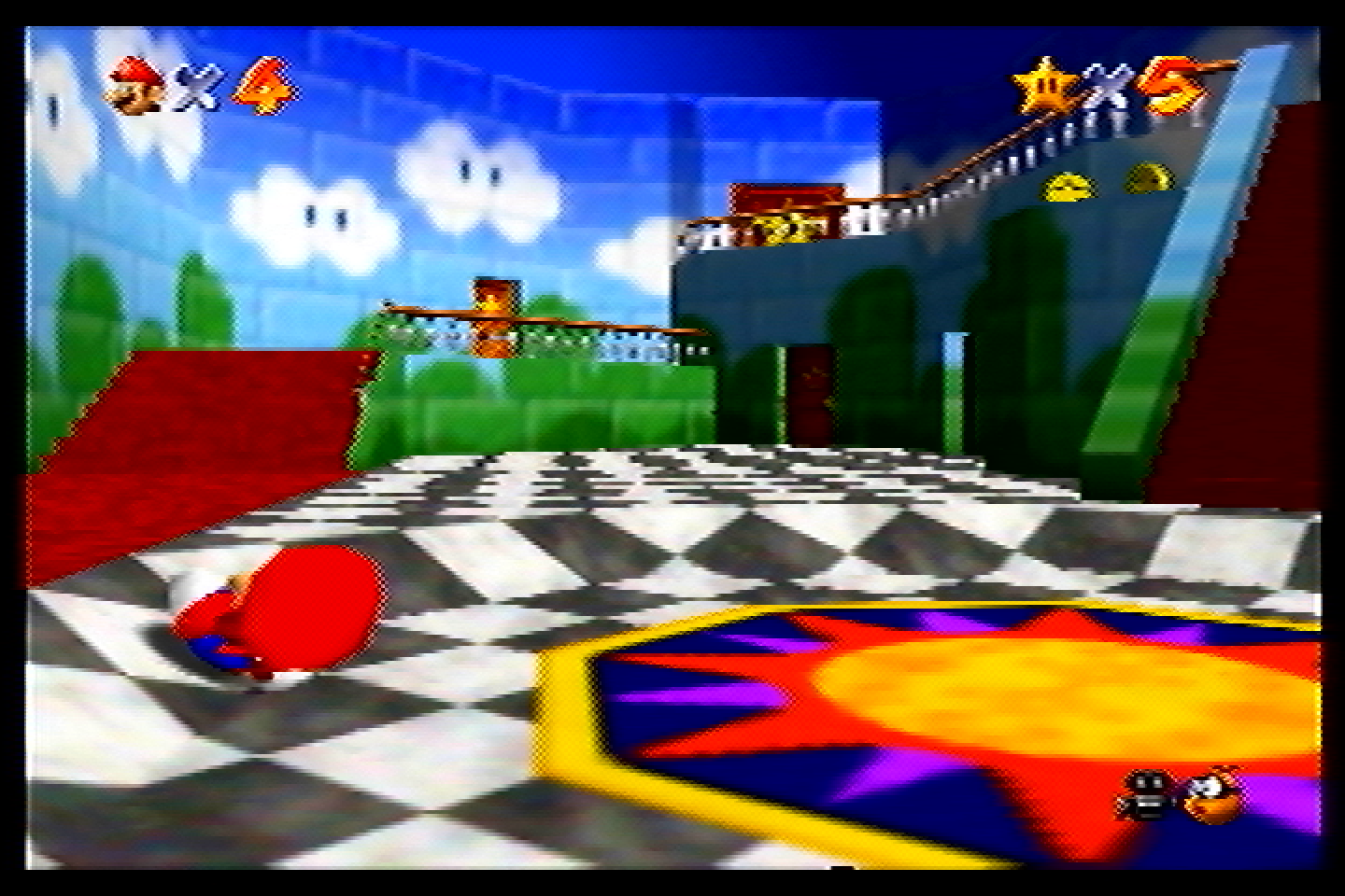
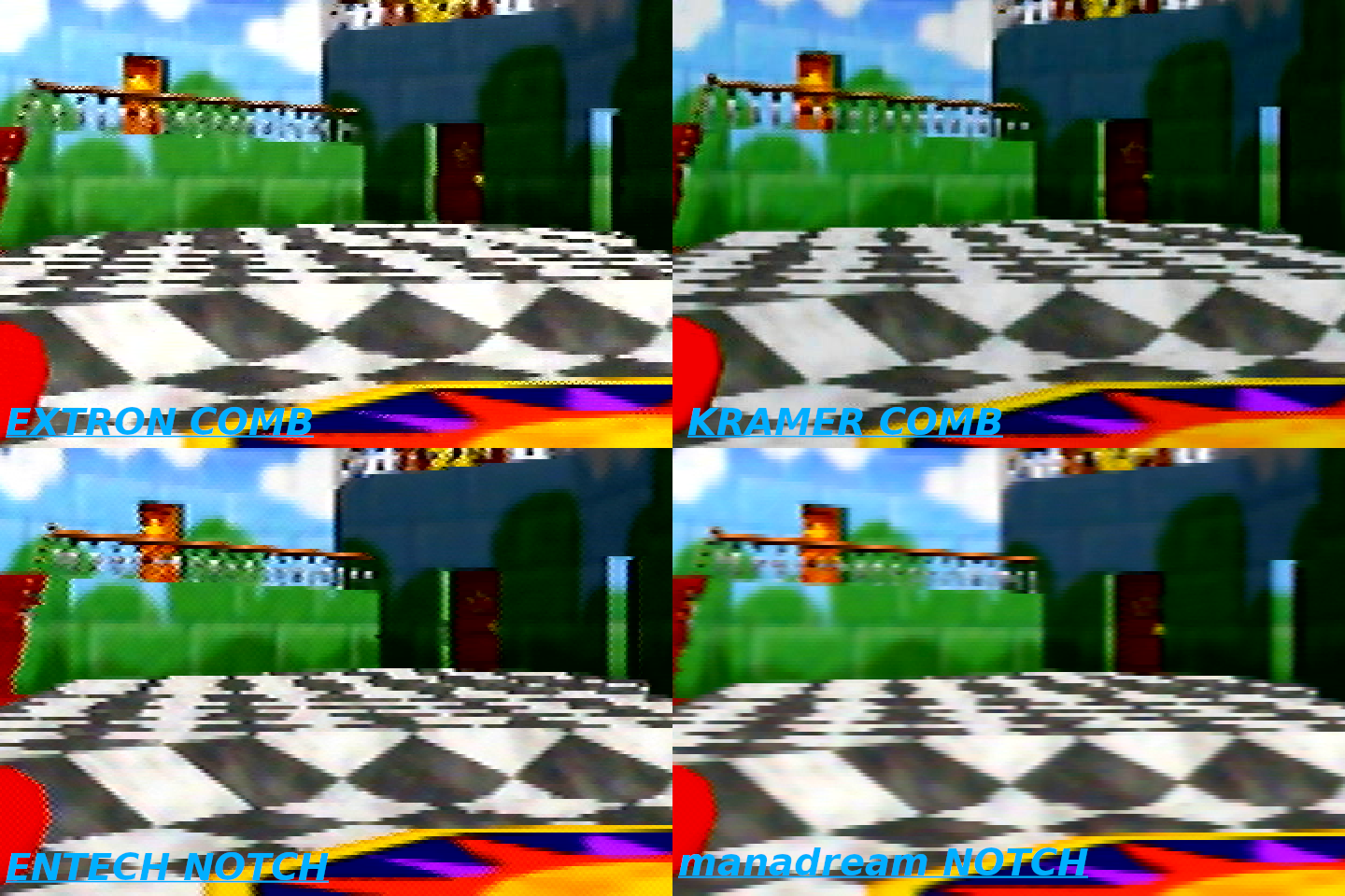
The railing and large star door in Mario 64.</li>
  <li>
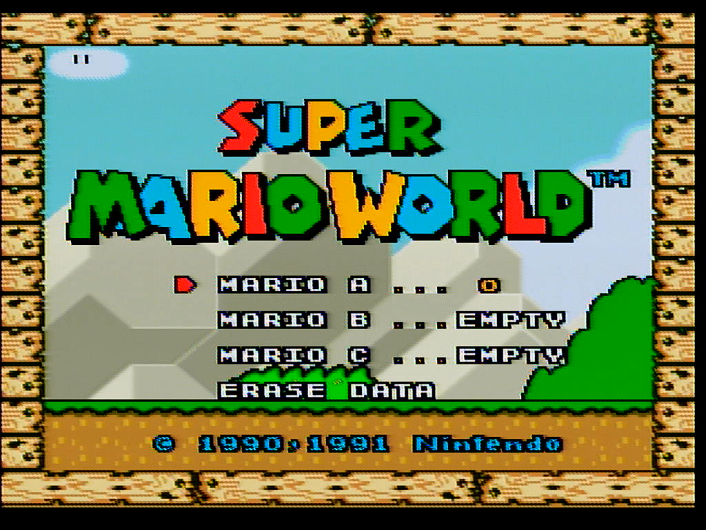
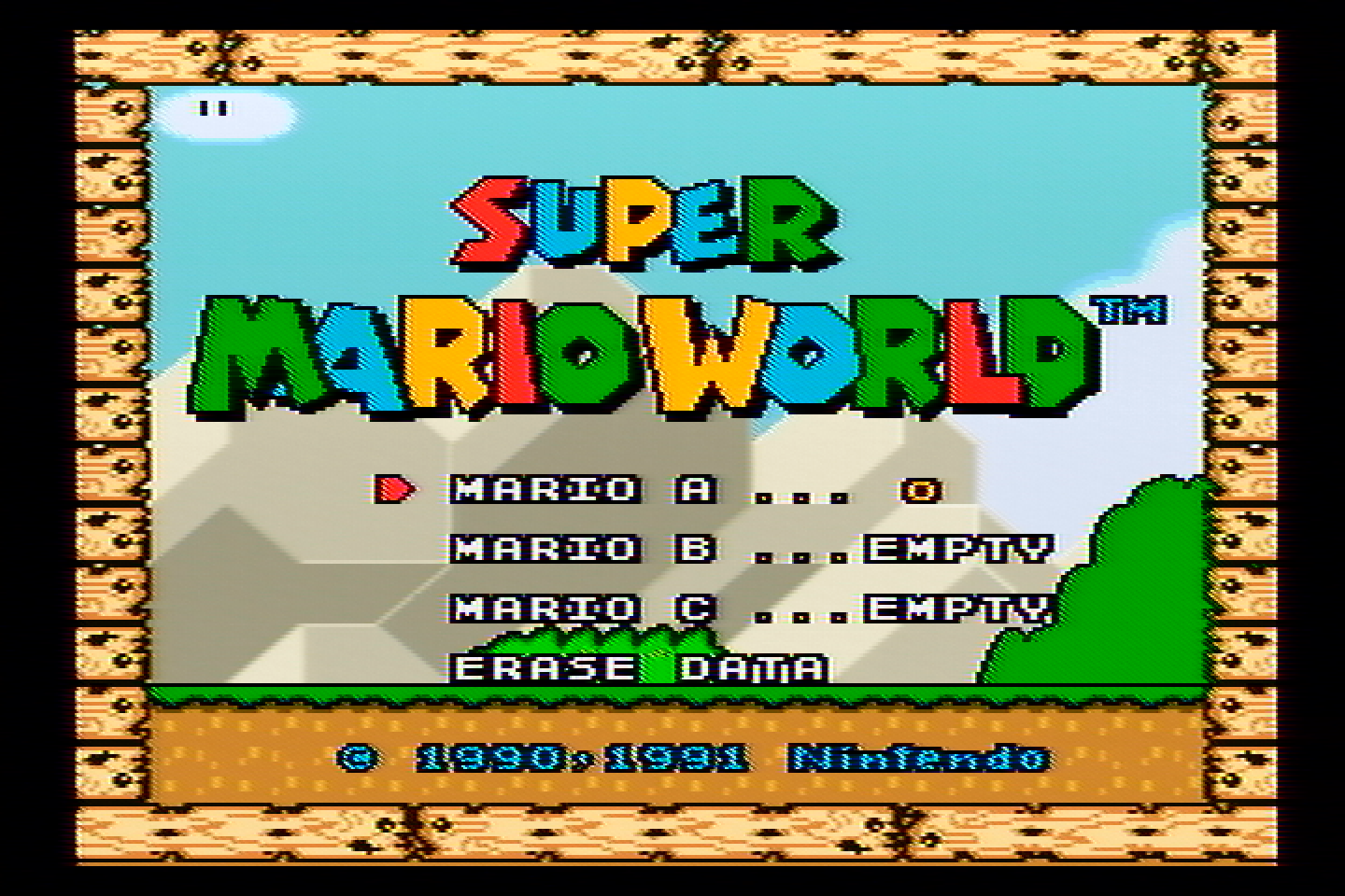
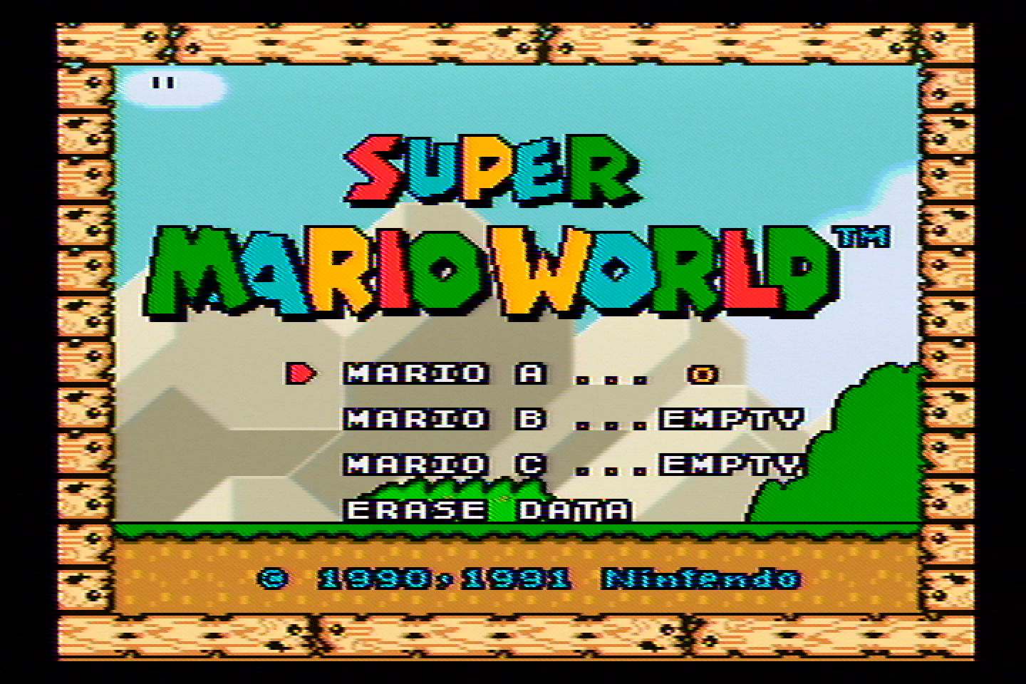
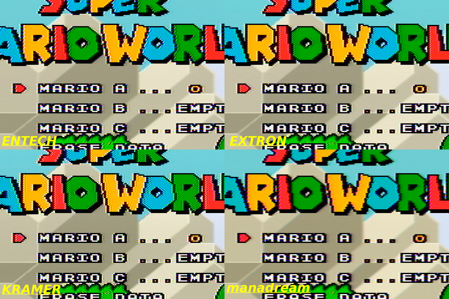
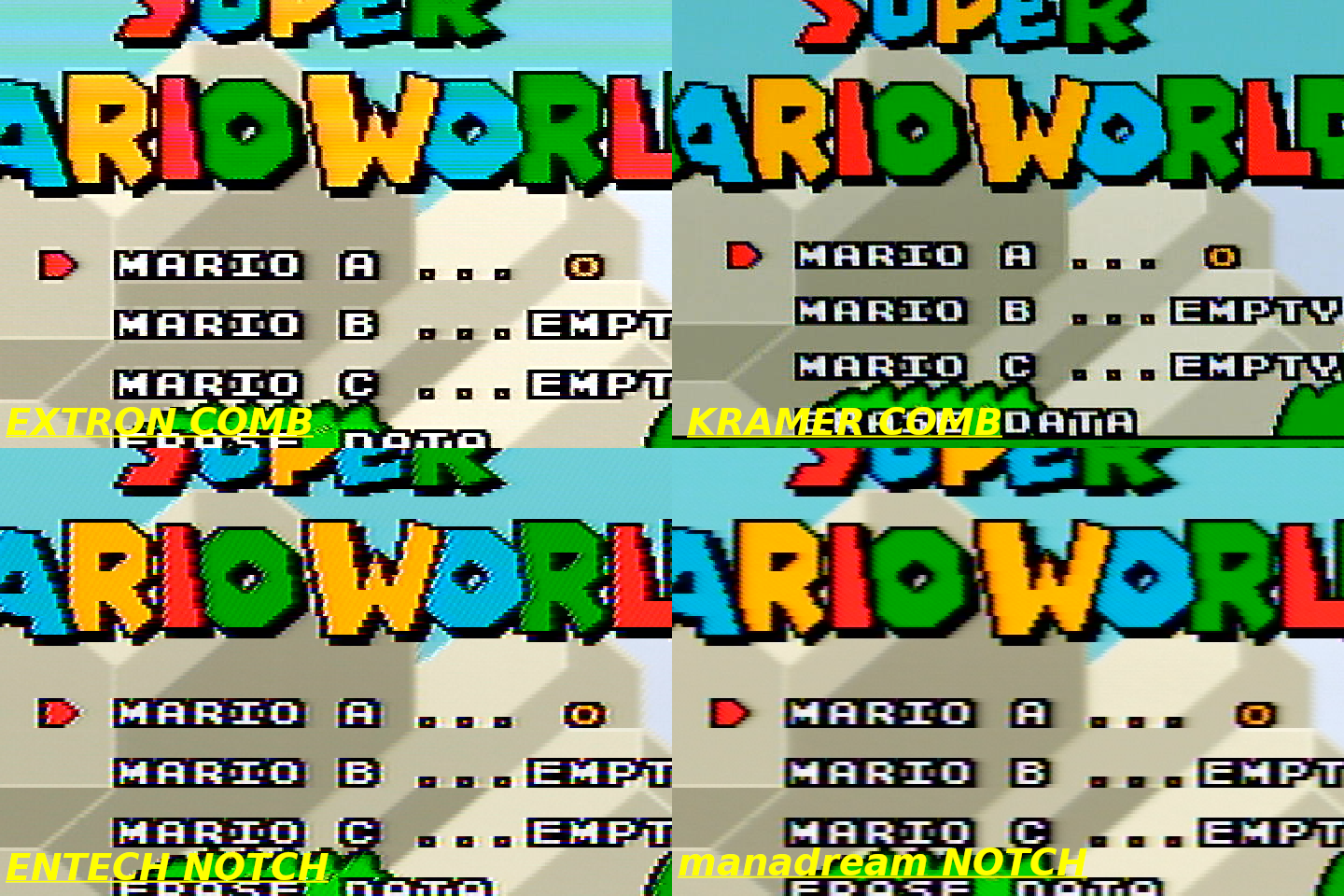
The top and bottom lines of text and graphics in Super Mario World</li>
  <li>
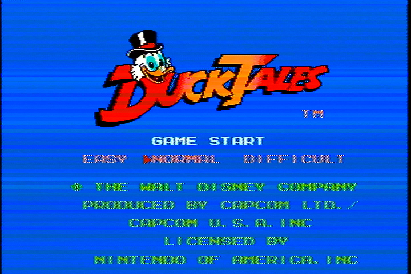
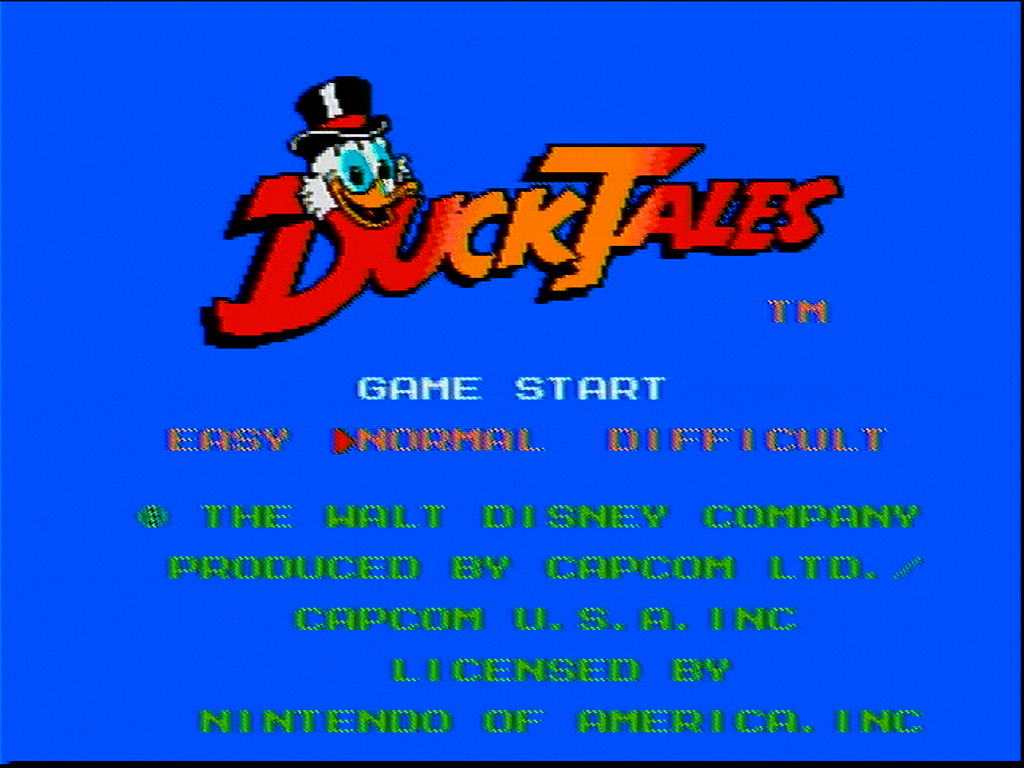
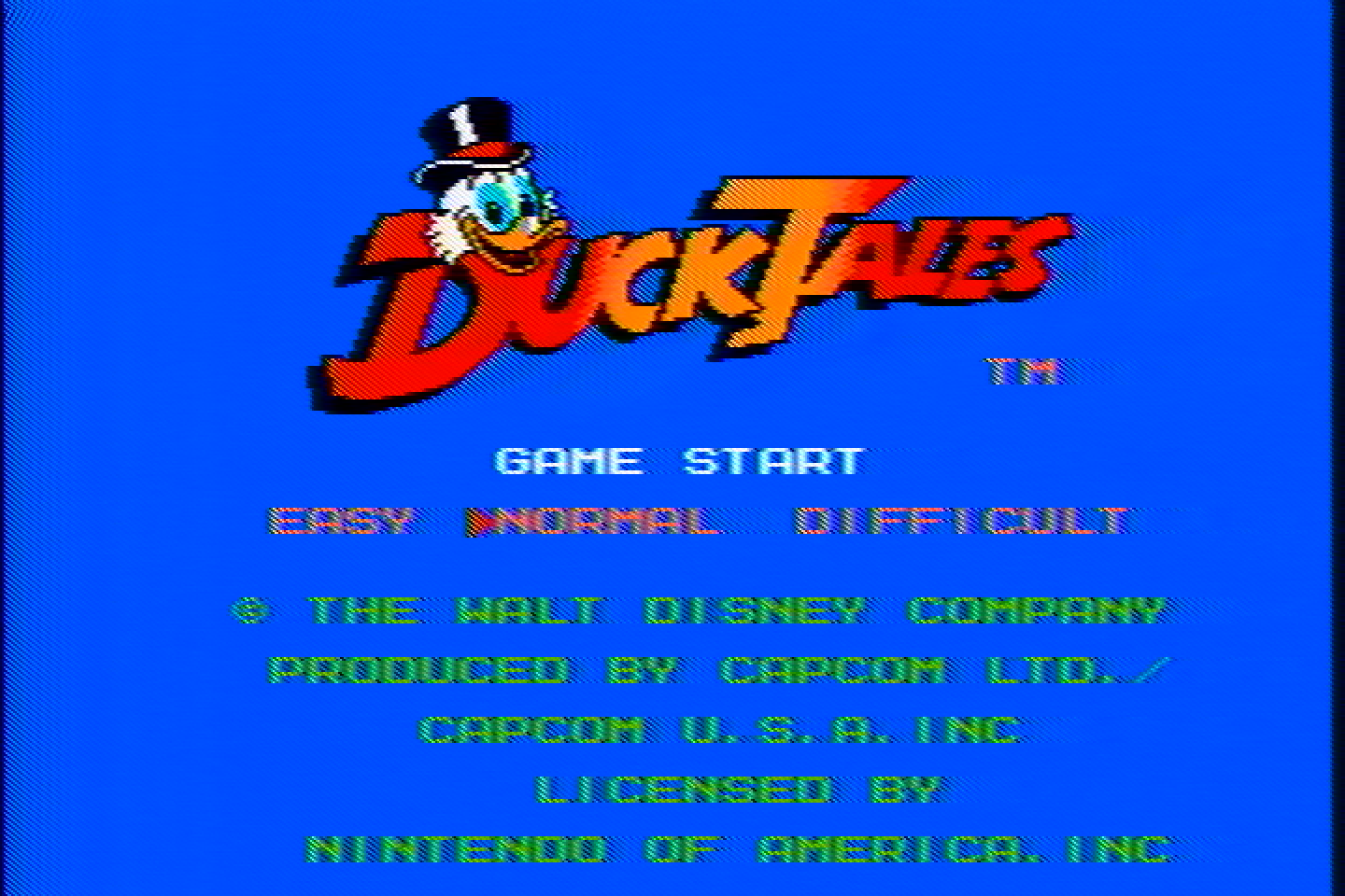
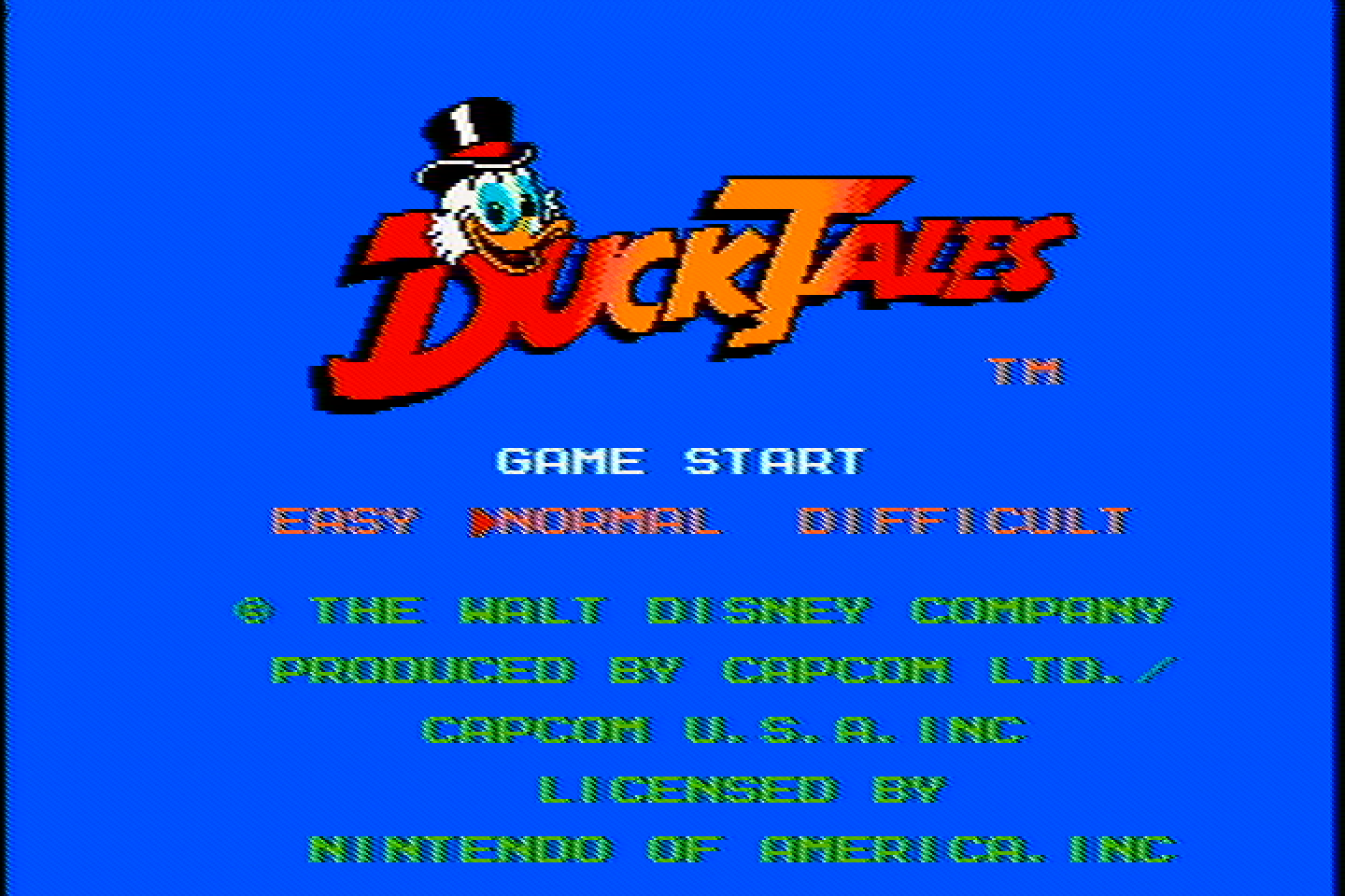
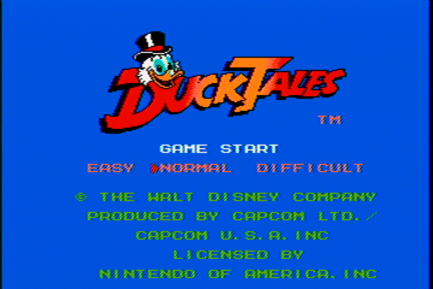
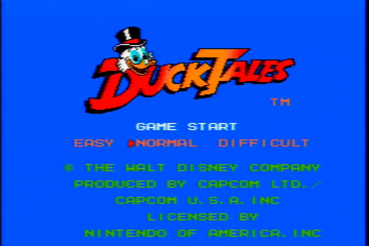
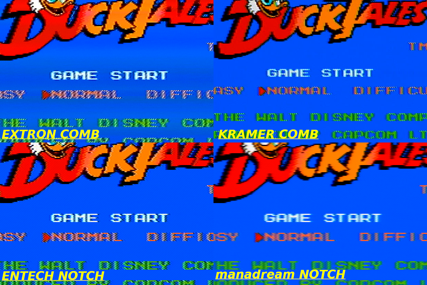
The text in Duck Tales</li>
</ul>

<p>Lots of CRTs have 2-line and 3-line comb filters built into them, so the picture will look something like this (minus the weird color banding).</p>

<h3 id="kramer-vp-413-3d-comb-filter">Kramer VP-413 (3D Comb Filter)</h3>

<p><img src="/assets/img/IMG_20251204_123442.jpg" alt="VP-413" /></p>

<p>
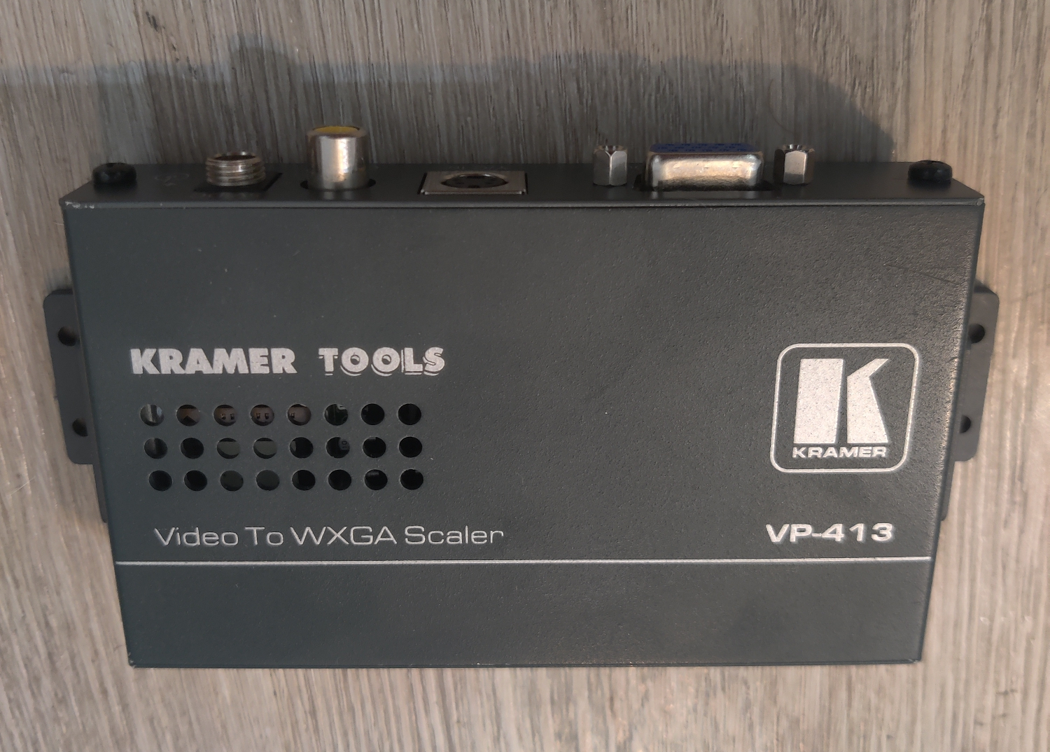
I bought this on Ebay for $27. It converts Composite to VGA using a very sophisticated 3D comb filter which represents the most advanced type of comb filters available. As you will see, it has some of the same problems as the 3-Line comb above, but not as badly.</p>

<p>One thing to note is that sophisticated comb filters like this one can also revert to a Notch filter if the hardware decides that would be better for whatever reason it’s programmed to. That seems to be the case with Sega Genesis video content for some reason. So the screenshots of Genesis games will look more like what a Notch filter would, although the notch in this device is pretty bad and has a lot of rainbowing, as you’ll see.</p>

<p><img src="/assets/img/Kramer%20VP-413%2007.png" alt="240p Menu" />
<img src="/assets/img/Kramer%20VP-413%2006.png" alt="SMTP Color Bars" />
<img src="/assets/img/Kramer%20VP-413%2005.png" alt="240p Girl" />
<img src="/assets/img/Kramer%20VP-413%2004.png" alt="SoR2" />
<img src="/assets/img/Kramer%20VP-413%2008.png" alt="Sonic" />
<img src="/assets/img/Kramer%20VP-413%2003.png" alt="Mario 64" />
<img src="/assets/img/Kramer%20VP-413%2002.png" alt="SMW" />
<img src="/assets/img/Kramer%20VP-413%2001.png" alt="Duck Tales" /></p>

<p>As you can see, the Genesis content has a lot of rainbowing and does not demonstrate hanging dots like the N64, SNES and NES. This is why I say it is reverting to a notch for that video content as notch filters do not exhibit hanging dots (they do exhibit other dot artifacts that are common to both notch and comb filters, as you’ll see).</p>

<p>You can see clearly the presence of typical comb hanging dot artifacts in:</p>

<ul>
  <li>The railing, large star door, some parts of the Sun floor pattern, and the top of the coins in Mario 64.</li>
  <li>The top and bottom of the text in Duck Tales.</li>
  <li>The top and bottom lines of the border graphic in Super Mario World.</li>
</ul>

<p>It does do a better job than the 3-line comb, but it still has dot artifacts that all comb filters have.</p>

<h2 id="notch-filter-comparisons">Notch Filter Comparisons</h2>

<p>
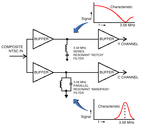
Notch filters work by splitting the Composite vide signal into Luma (Y) and Chroma (C) signals using a band-stop filter (also called a notch filter) for the Luma part of the signal and a band-pass filter for the Chroma part of the signal.</p>

<p><img src="/assets/img/ntscdb2fig2.png" alt="notch filter diagram" /></p>

<p><a href="https://crtdatabase.com/articles/decoding-240p">This article by Eli Krause</a> goes into detail explaining how this works, as well as how comb filters work and the technical differences. It is a relatively short and informative read which I recommend checking out if you want to understand better what is going on with these filters.</p>

<p>
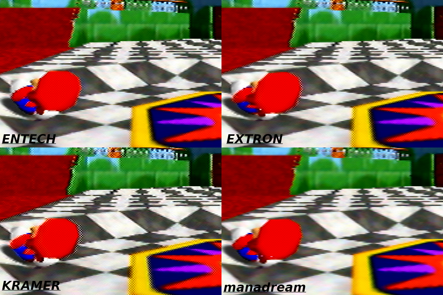
I purchased 4 different notch filters to compare to each other, and to <a href="https://manadream.shop/product/notch-filter-composite-to-s-video-converter">the one I have made</a>. I will go over each one and talk about how they compare to each other.</p>

<p>All comparisons were done using an I-O DATA GV-USB2 S-Video capture device and the following consoles’ composite output:</p>

<ul>
  <li>Sega Genesis Model 1 VA 6.5, recapped with no mods</li>
  <li>NES-001 Front Loader, recapped and modded with Lava RGB v1</li>
  <li>SNES SHVC-CPU-01, recapped with no mods</li>
  <li>N64 NUS-CPU-04, recapped with no mods</li>
</ul>

<p>Again, the 240p Test Suite images are from the Sega Genesis. This console has some jailbars and pretty bad rainbowing, so the video isn’t the best, but I think it is a good test because it shows how well different filters handle the imperfect video, plus this is what most stock Genesis consoles are going to look like.</p>

<h3 id="tributaries-c2s">Tributaries C2S</h3>

<p><img src="/assets/img/Tributaries.jpg" alt="C2S" /></p>

<p>
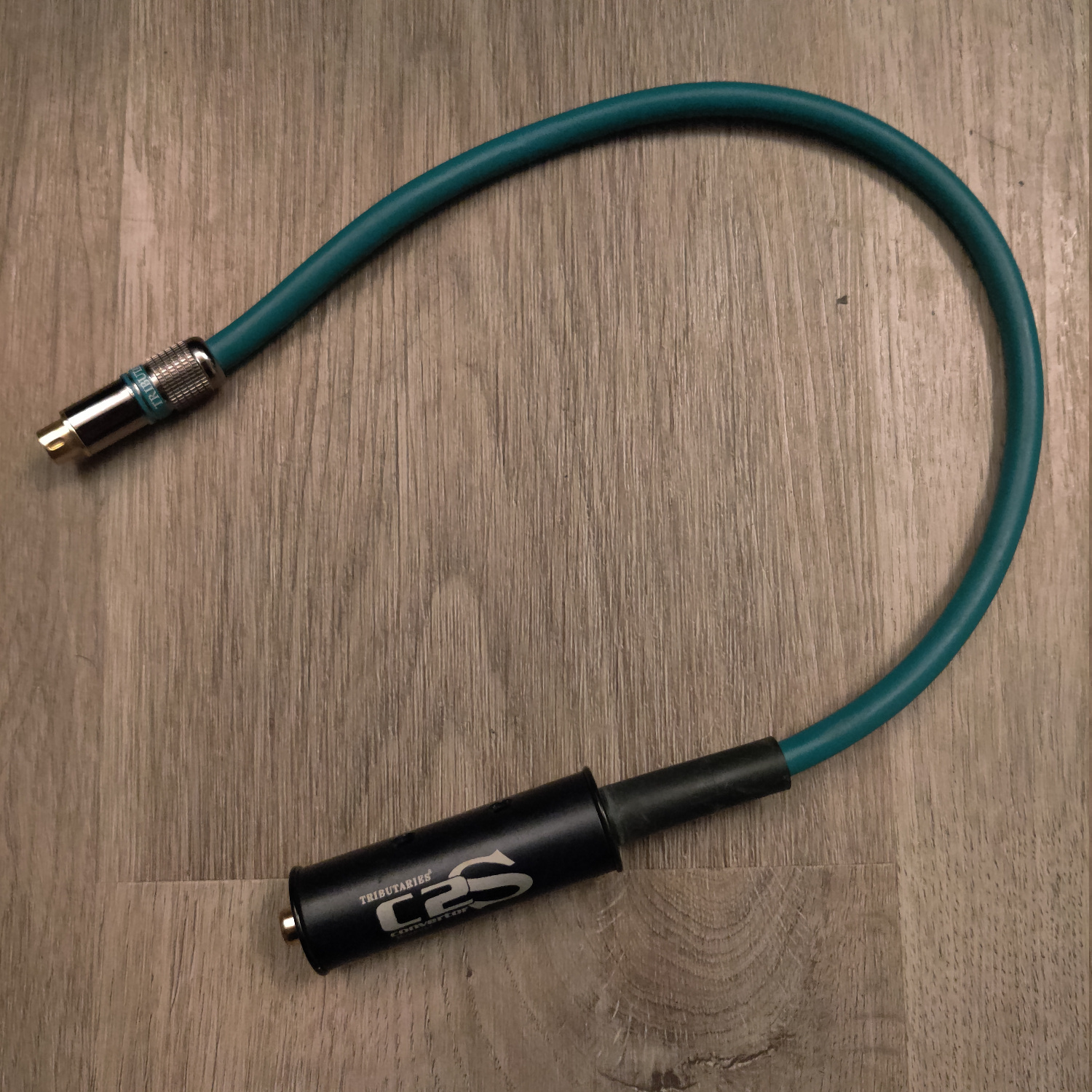
I bought this on eBay for about $30, but I’m not sure how easy they are to find.</p>

<p><img src="/assets/img/Tributaries%2007.png" alt="240p Menu" />
<img src="/assets/img/Tributaries%2006.png" alt="SMTP Color Bars" />
<img src="/assets/img/Tributaries%2005.png" alt="240p Girl" />
<img src="/assets/img/Tributaries%2004.png" alt="SoR2" />
<img src="/assets/img/Tributaries%2008.png" alt="Sonic" />
<img src="/assets/img/Tributaries%2003.png" alt="Mario 64" />
<img src="/assets/img/Tributaries%2002.png" alt="SMW" />
<img src="/assets/img/Tributaries%2001.png" alt="Duck Tales" /></p>

<p>It has noticeable ghosting/echoing which is very obvious on the right side of Mario’s hat in the Mario 64 pic.
It also has a lot of dot crawl, so I don’t recommend it.</p>

<h3 id="kramer-401d">Kramer 401D</h3>

<p><img src="/assets/img/Kramer.jpg" alt="401D" /></p>

<p>
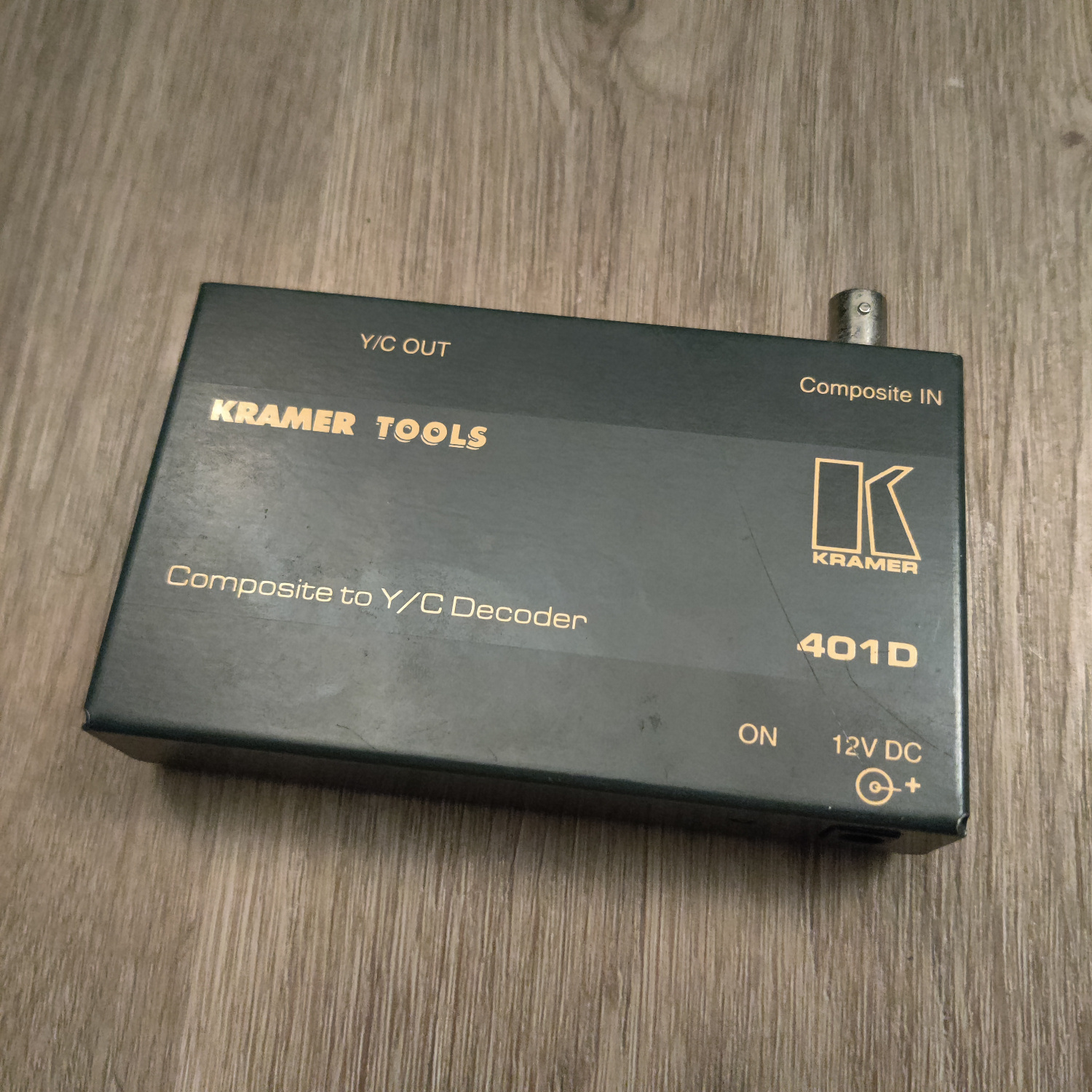
I got this one as a gift, but it looks like they can go for around $15-$90 on eBay. It has a BNC connector for Composite video.</p>

<p><img src="/assets/img/Kramer%2007.png" alt="240p Menu" />
<img src="/assets/img/Kramer%2006.png" alt="SMTP Color Bars" />
<img src="/assets/img/Kramer%2005.png" alt="240p Girl" />
<img src="/assets/img/Kramer%2004.png" alt="SoR2" />
<img src="/assets/img/Kramer%2008.png" alt="Sonic" />
<img src="/assets/img/Kramer%2003.png" alt="Mario 64" />
<img src="/assets/img/Kramer%2002.png" alt="SMW" />
<img src="/assets/img/Kramer%2001.png" alt="Duck Tales" /></p>

<p>The dot crawl on this one is very bad, especially on Duck Tales. It doesn’t have as much ghosting/echoing as the Tributaries though.</p>

<h3 id="extron-vyc-100n">Extron VYC 100N</h3>

<p><img src="/assets/img/Extron.jpg" alt="VYC 100N" /></p>

<p>I purchased this one for about $30 on eBay, there are quite a few of these available on eBay. 
It has a BNC connector for Composite video, and two BNC connectors for S-Video in addition to the standard 4-pin S-Video connector.</p>

<p><img src="/assets/img/Extron%2007.png" alt="240p Menu" />
<img src="/assets/img/Extron%2006.png" alt="SMTP Color Bars" />
<img src="/assets/img/Extron%2005.png" alt="240p Girl" />
<img src="/assets/img/Extron%2004.png" alt="SoR2" />
<img src="/assets/img/Extron%2008.png" alt="Sonic" />
<img src="/assets/img/Extron%2003.png" alt="Mario 64" />
<img src="/assets/img/Extron%2002.png" alt="SMW" />
<img src="/assets/img/Extron%2001.png" alt="Duck Tales" /></p>

<p>
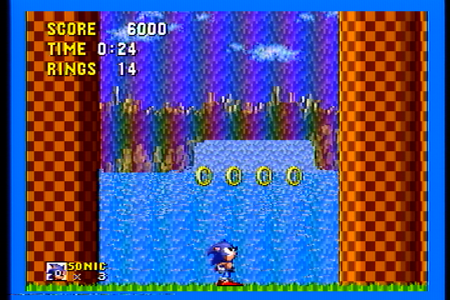
The dot crawl on this one is better than the Tributaries and the Kramer, though the rainbow artifacts are about the same (which you can see on the left side of the white text in the SMW screens and in the Sonic image).</p>

<h3 id="entech-csvc-1">Entech CSVC-1</h3>

<p><img src="/assets/img/Entech.jpg" alt="CSVC-1" /></p>

<p>Thanks to kitty666cats/Mike Lindquist, a fellow member of the CRT community, I got this one for about $30 <a href="https://www.ebay.com/itm/227126035252">on eBay</a>. It has a male RCA connector, so I had to use a coupler to connect it to the male RCA connectors from my consoles.</p>

<p><img src="/assets/img/Entech%2007.png" alt="240p Menu" />
<img src="/assets/img/Entech%2006.png" alt="SMTP Color Bars" />
<img src="/assets/img/Entech%2005.png" alt="240p Girl" />
<img src="/assets/img/Entech%2004.png" alt="SoR2" />
<img src="/assets/img/Entech%2008.png" alt="Sonic" />
<img src="/assets/img/Entech%2003.png" alt="Mario 64" />
<img src="/assets/img/Entech%2002.png" alt="SMW" />
<img src="/assets/img/Entech%2001.png" alt="Duck Tales" /></p>

<p>This one has less dot crawl and rainbow artifacts than the Tributaries, Kramer and Extron. It still exhibits a fair bit of dot crawl on NES games however.</p>

<h3 id="manadream-notch-filter">manadream Notch Filter</h3>

<p><img src="/assets/img/manadream.jpg" alt="manadream notch filter" /></p>

<p>Full disclosure, I designed this filter myself with the goal of being better for retro gaming than anything available on the market.
I believe I have accomplished this goal, but you can decide for yourself.</p>

<p>This filter comes with a knob that lets you adjust the strength of the filter, and thus the sharpness of the picture.
It is the nature of a notch filter that the stronger it is, the more frequencies it will cut from the Luma signal, and thus the more blending there will be.
The goal is to dial it in for your specific TV set to get the sharpest image possible that also does not have dot artifacts.</p>

<p>These images are all captured with the sharpness knob at maximum sharpness.</p>

<p><img src="/assets/img/manadream%20max%20sharp%2007.png" alt="240p Menu" />
<img src="/assets/img/manadream%20max%20sharp%2006.png" alt="SMTP Color Bars" />
<img src="/assets/img/manadream%20max%20sharp%2005.png" alt="240p Girl" />
<img src="/assets/img/manadream%20max%20sharp%2004.png" alt="SoR2" />
<img src="/assets/img/manadream%20max%20sharp%2008.png" alt="Sonic" />
<img src="/assets/img/manadream%20max%20sharp%2003.png" alt="Mario 64" />
<img src="/assets/img/manadream%20max%20sharp%2002.png" alt="SMW" />
<img src="/assets/img/manadream%20max%20sharp%2001.png" alt="Duck Tales" /></p>

<p>It’s very similar to the Entech filter, though with more vibrant colors and slightly less dot crawl and less ghosting.</p>

<p>But if we sacrifice just a little bit of sharpness, we can eliminate a lot of it.</p>

<p>These images were captured with the sharpness knob at 75% of max sharpness.</p>

<p><img src="/assets/img/manadream%20less%20sharp%2007.png" alt="240p Menu" />
<img src="/assets/img/manadream%20less%20sharp%2006.png" alt="SMTP Color Bars" />
<img src="/assets/img/manadream%20less%20sharp%2005.png" alt="240p Girl" />
<img src="/assets/img/manadream%20less%20sharp%2004.png" alt="SoR2" />
<img src="/assets/img/manadream%20less%20sharp%2008.png" alt="Sonic" />
<img src="/assets/img/manadream%20less%20sharp%2003.png" alt="Mario 64" />
<img src="/assets/img/manadream%20less%20sharp%2002.png" alt="SMW" />
<img src="/assets/img/manadream%20less%20sharp%2001.png" alt="Duck Tales" /></p>

<p>As you can see, the dot crawl is significantly reduced. It can be reduced even further by lowering the sharpness more.</p>

<p>On a CRT, the visible sharpness difference between 100% sharp and 75% sharp is going to be barely noticeable, especially from a normal viewing distance.</p>

<p>Having this sharpness knob allows you to dial in the sharpness vs dot artifacts to your preference.</p>

<p>The way these results are achieved is by having multiple stages of filtering in addition to video amplification.</p>

<p>The manadream Notch Filter is a proper, 75-ohm input terminated, 75-ohm output impedance video filter and amplifier for NTSC composite video.
You’ll notice more vibrant colors and a brighter picture than other filters using this filter.</p>

<p>The manadream Notch Filter is available for purchase <a href="https://manadream.shop/product/notch-filter-composite-to-s-video-converter">on my store</a>. I also sell other retro gaming products and modding services, let me know if there’s something you’d like that I don’t have listed!</p>

<h2 id="side-by-side-comparisons">Side-By-Side Comparisons</h2>

<p>Here are some of these filters compared side-by-side. I have chosen the images that show the differences most clearly.</p>

<h3 id="notch-side-by-sides">Notch Side-By-Sides</h3>

<p><img src="/assets/img/Side%20By%20Side%2001.png" alt="Side by Side 1" /></p>

<p><img src="/assets/img/Side%20By%20Side%2002.png" alt="Side by Side 2" /></p>

<p><img src="/assets/img/Side%20By%20Side%2003.png" alt="Side by Side 3" /></p>

<p><img src="/assets/img/Side%20By%20Side%2004.png" alt="Side by Side 4" /></p>

<h3 id="comb-and-notch-side-by-sides">
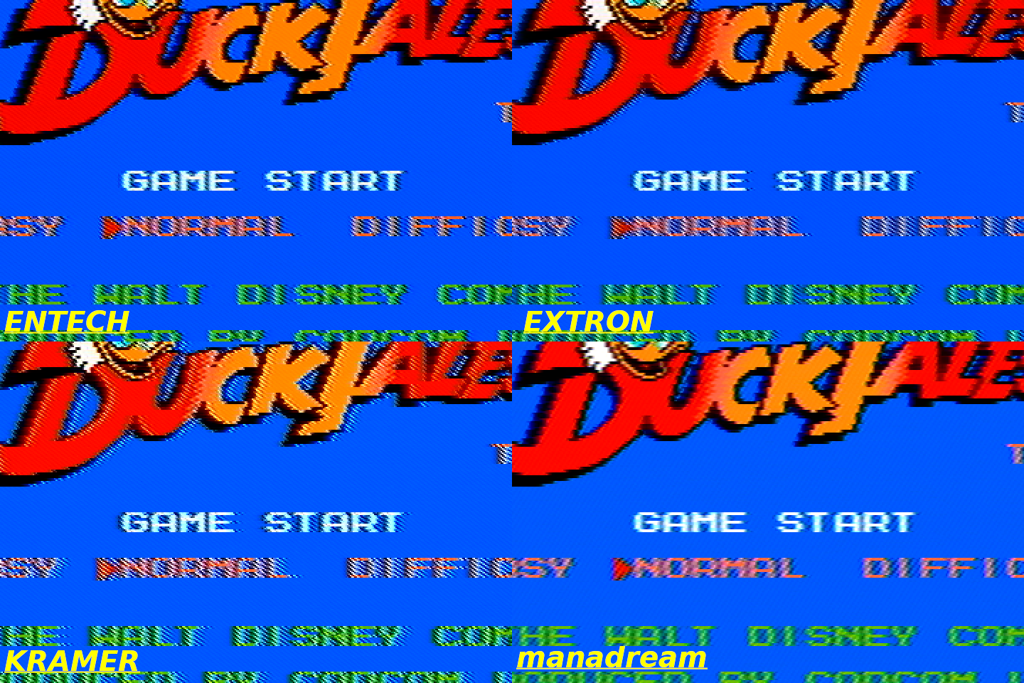
Comb and Notch Side-By-Sides
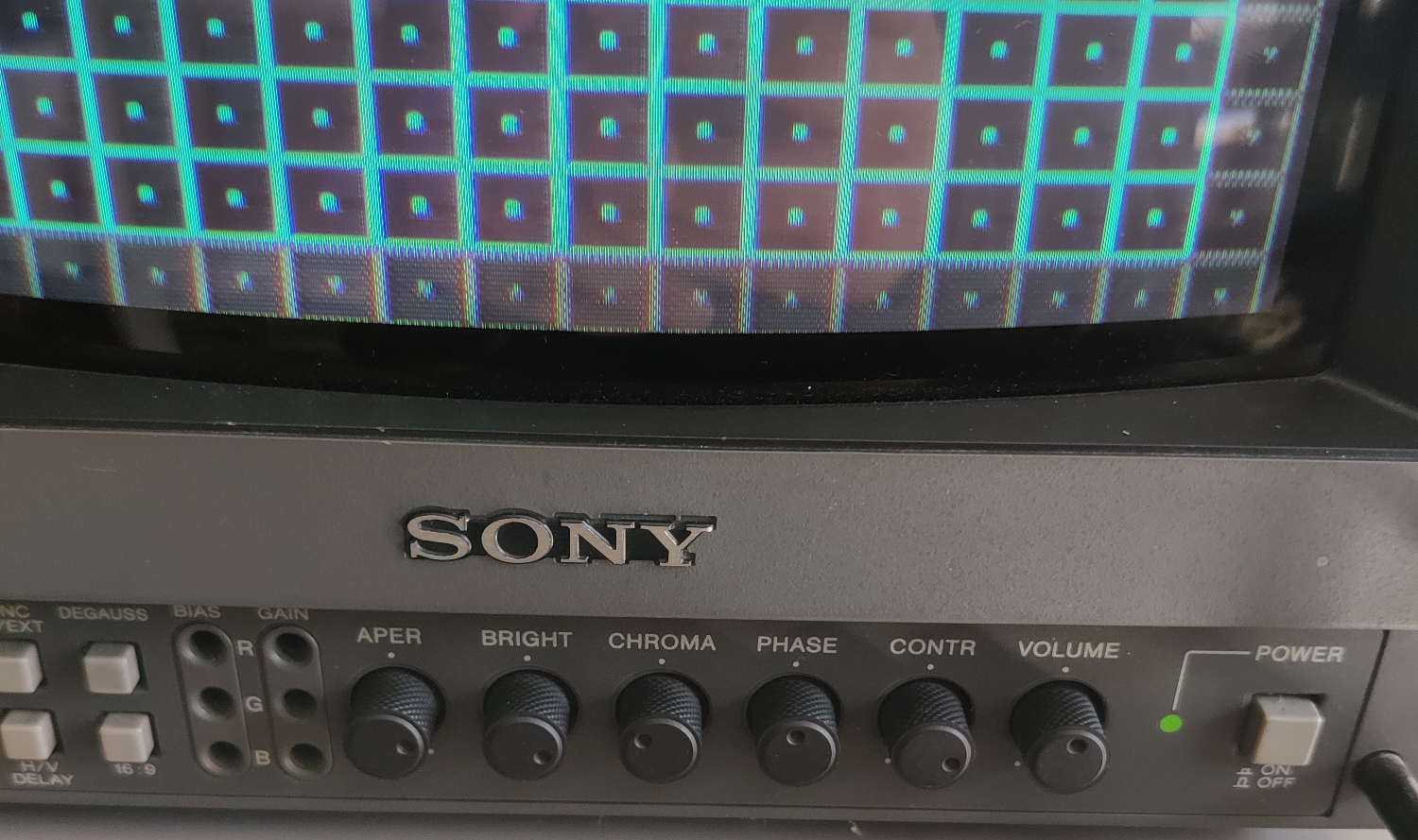
</h3>

<p><img src="/assets/img/Side%20By%20Side%2005.png" alt="Side by Side 5" /></p>

<p><img src="/assets/img/Side%20By%20Side%2006.png" alt="Side by Side 6" /></p>

<p><img src="/assets/img/Side%20By%20Side%2007.png" alt="Side by Side 7" /></p>

<p><img src="/assets/img/Side%20By%20Side%2008.png" alt="Side by Side 8" /></p>

<h2 id="bonus-images">Bonus Images</h2>

<p>These are some images/comparisons that were provided to me by others and/or are on CRTs instead of direct captures.
I’m showing them here to further demonstrate the difference between Comb filters and Notch filters in general.</p>

<p>
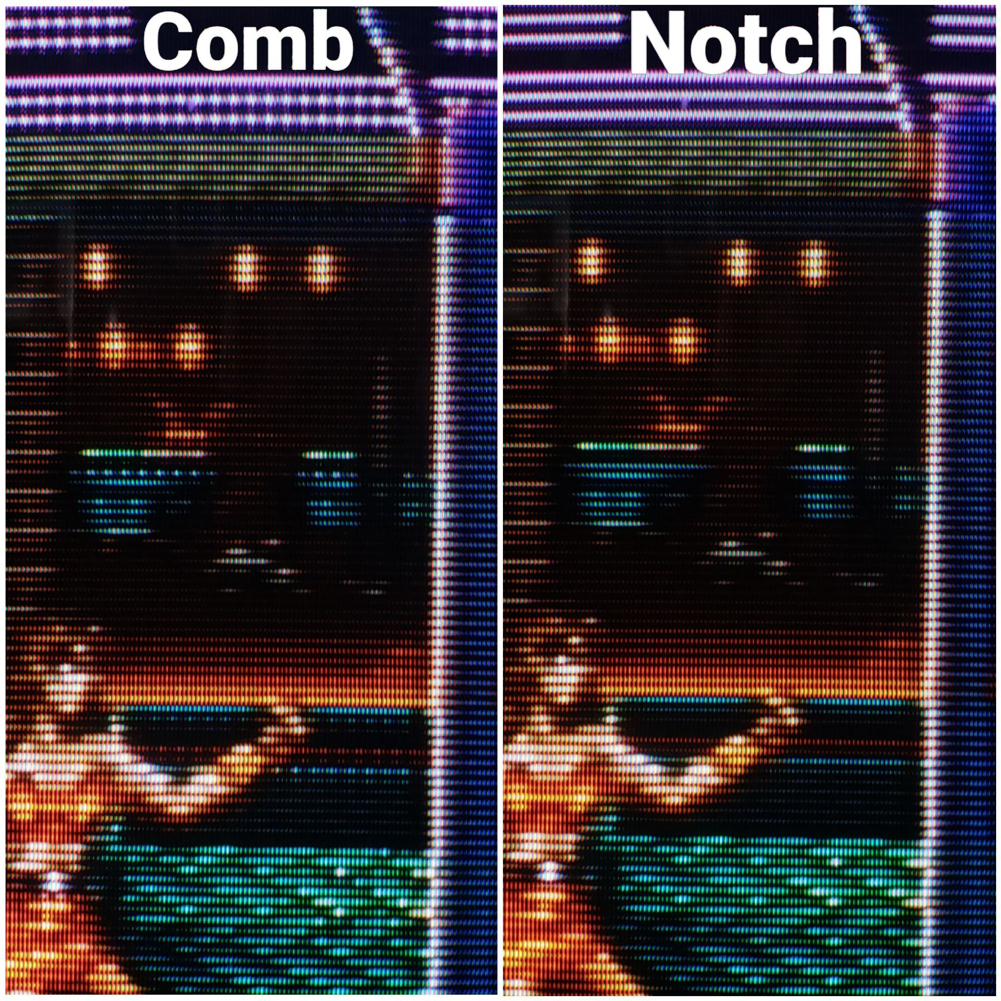
Comb filter dot artifacts on a PVM, you can see it in the red squares on the bottom very clearly (might need to open the image in a new tab and zoom in):</p>

<p><img src="/assets/img/IMG_20251205_000357.jpg" alt="PVM artifacts" /></p>

<p>Comb dot artifacts on an RCA set:</p>

<p><img src="/assets/img/IMG_20251124_202230.jpg" alt="RCA dot artifacts" /></p>

<p>
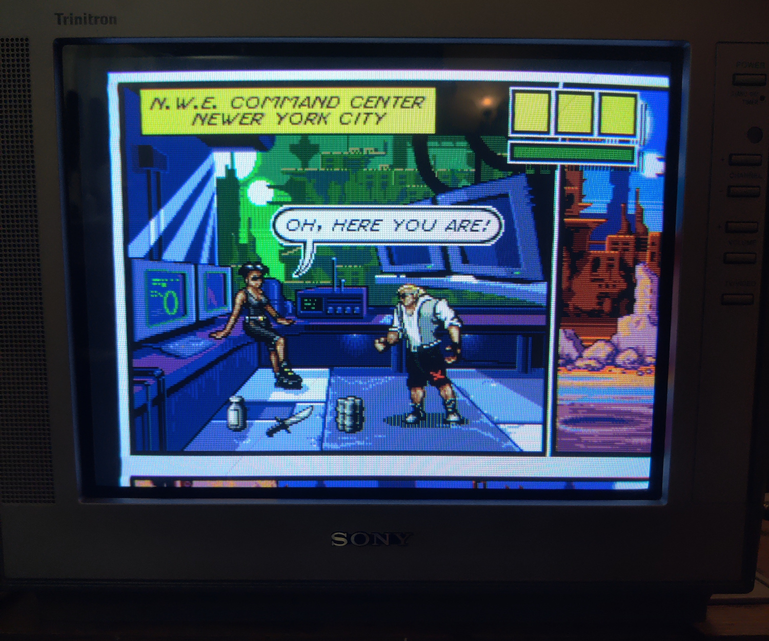
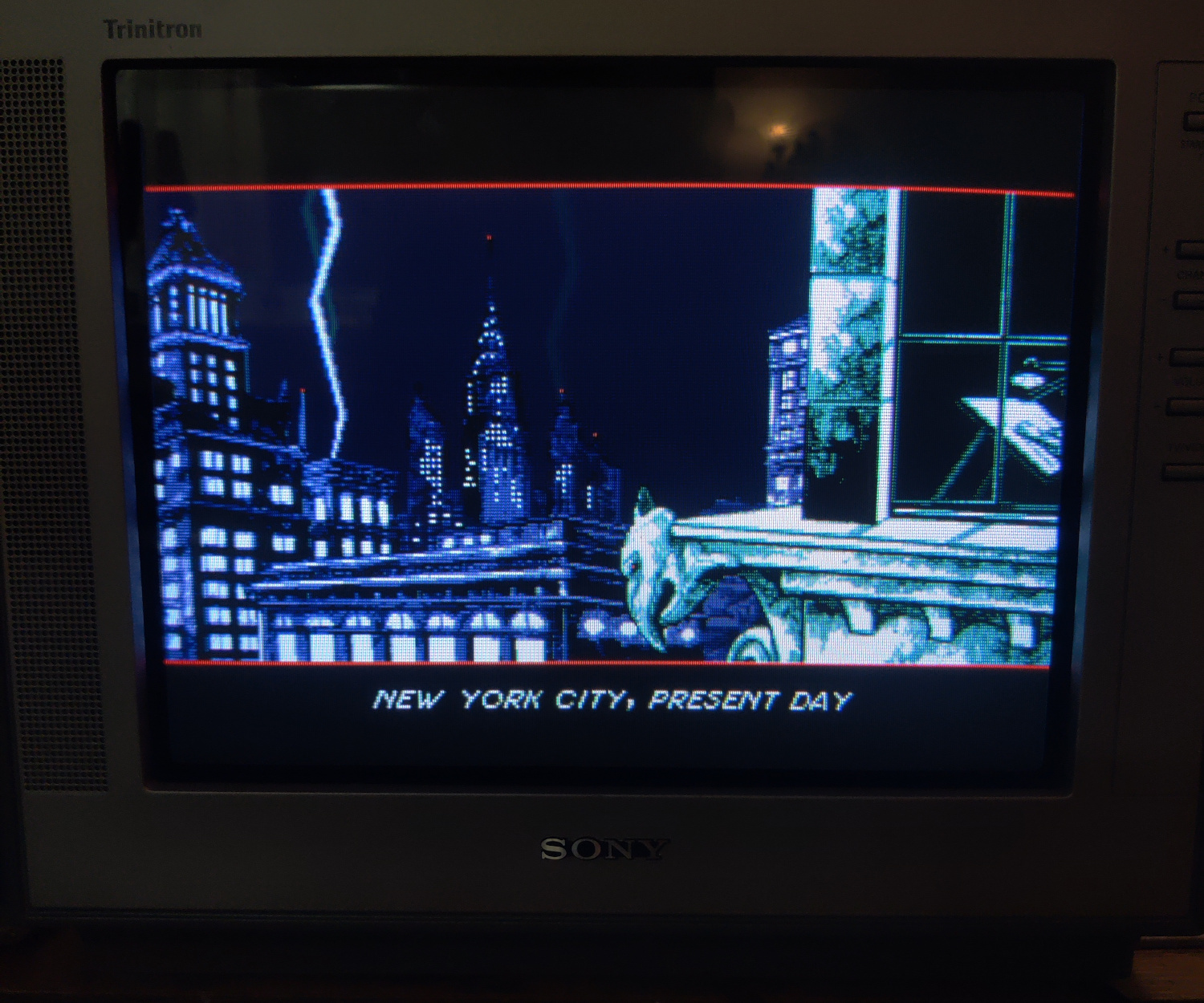
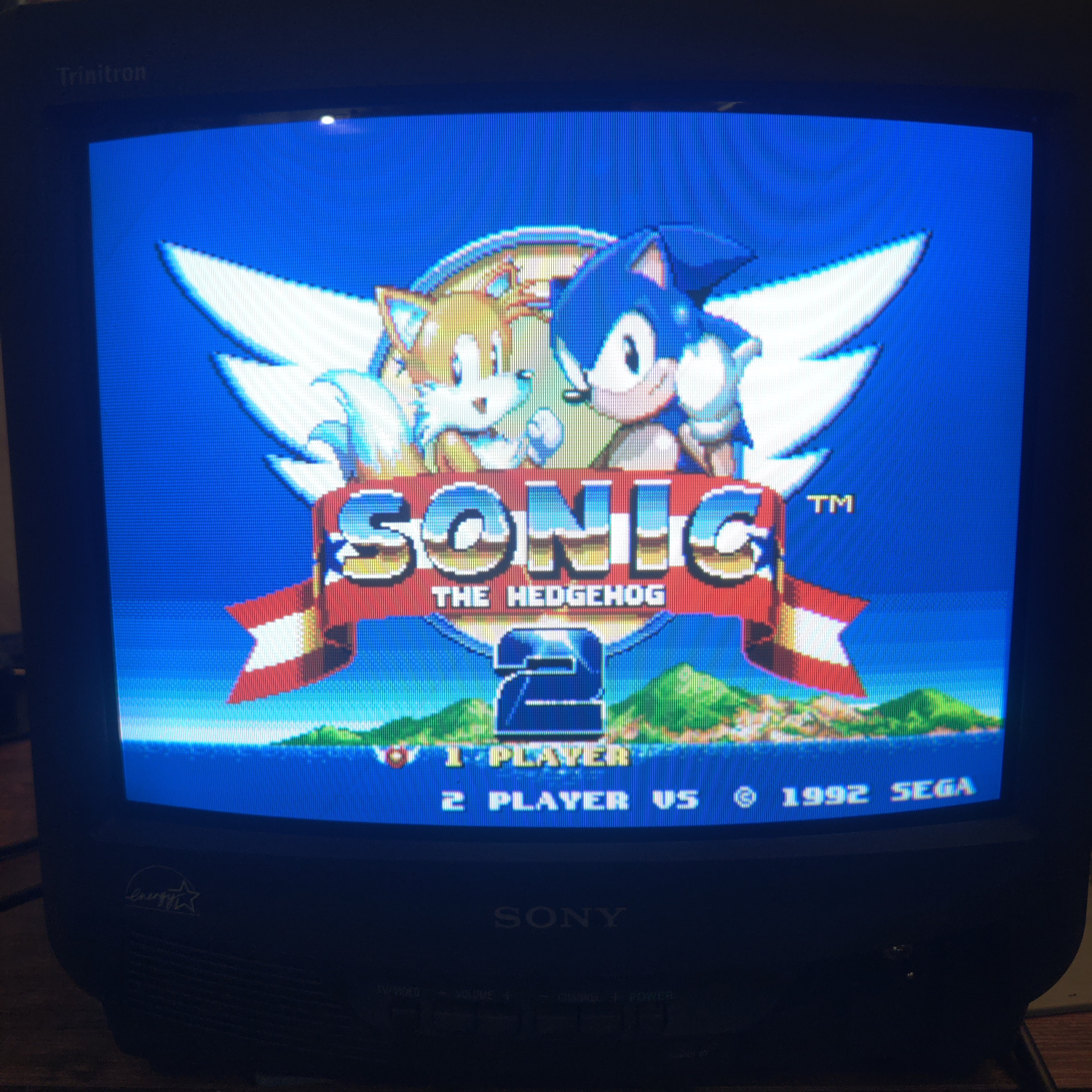
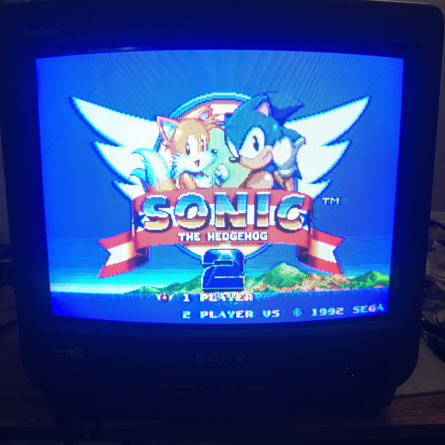
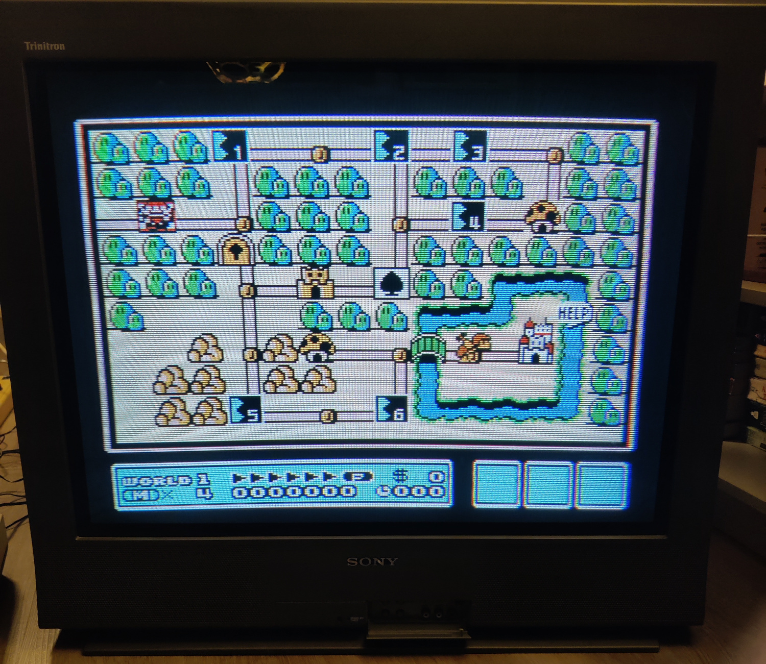
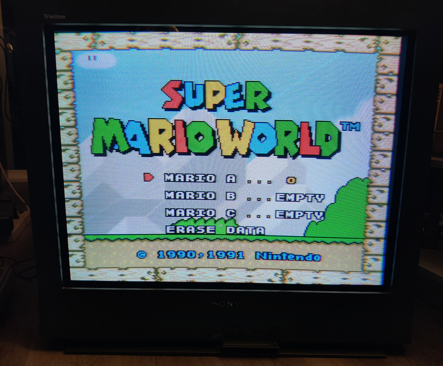
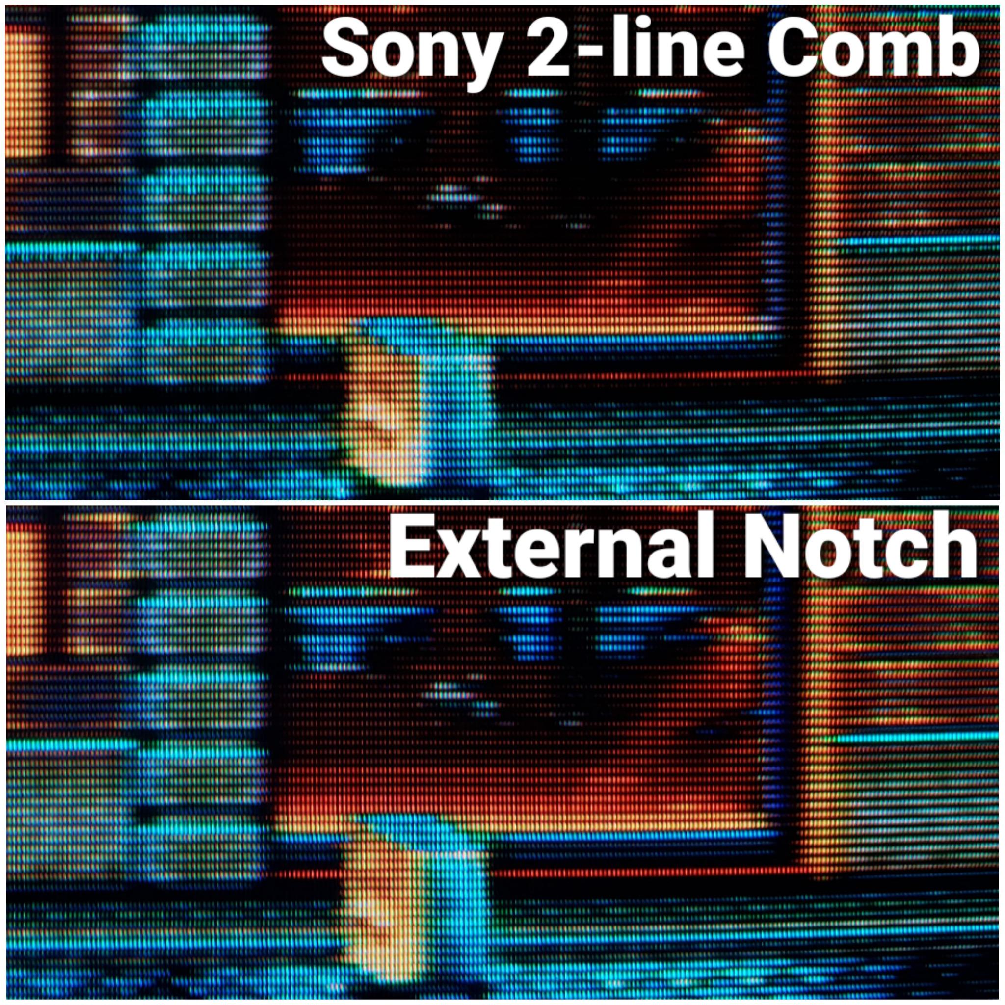
Comb dot artifacts on a Sony Trinitron, visible in the red text:</p>

<p><img src="/assets/img/IMG_20251202_013223.jpg" alt="Trinitron dot artifacts" /></p>

<p>
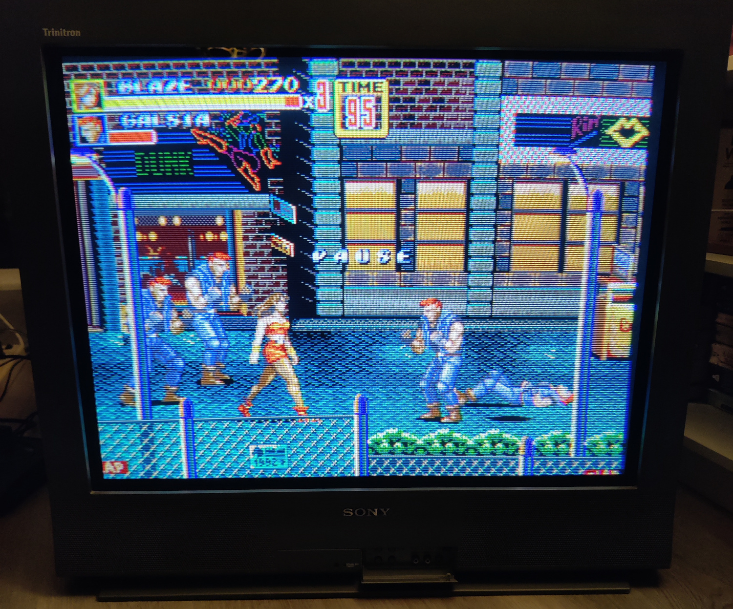
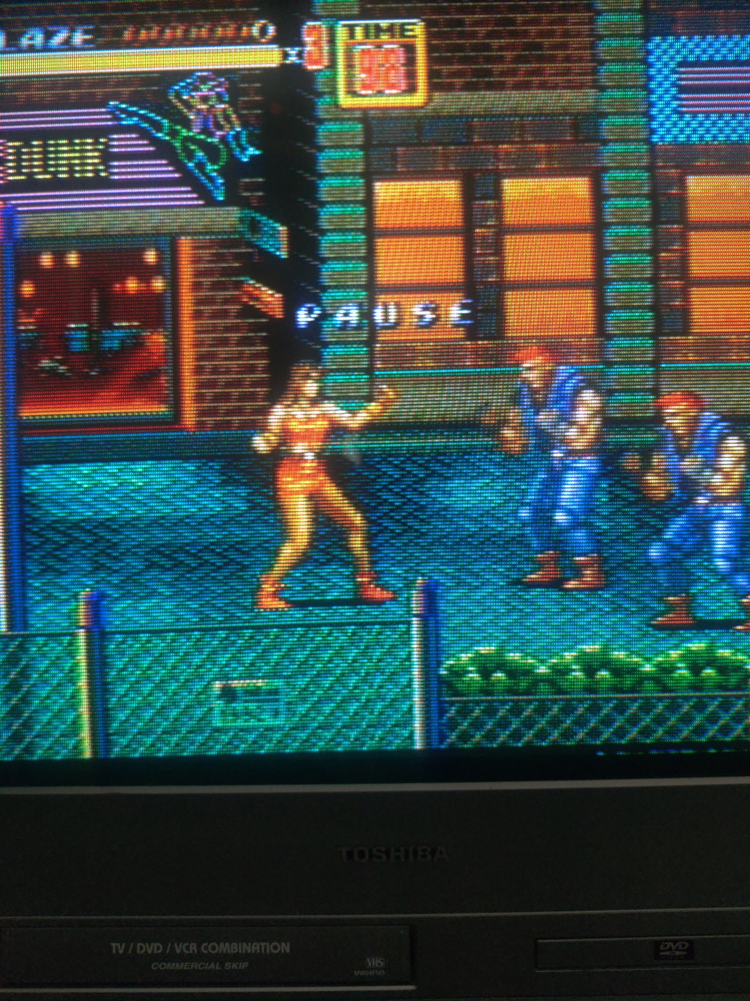
Streets of Rage 2 on a CRT:</p>

<p><img src="/assets/img/Example%201.jpg" alt="SoR2 1" /></p>

<p><img src="/assets/img/Example%202.jpg" alt="SoR2 2" /></p>

<p><img src="/assets/img/Example%203.jpg" alt="SoR2 3" /></p>

<p>An example of a really bad external Notch (in one of those tiny, inline adapters) not removing Chroma information from Luma, on a CRT:</p>

<p><img src="/assets/img/comp2svidbad.jpg" alt="bad notch adapter" /></p>

<p><img src="/assets/img/CRT%20Cheapo%20CV2.jpg" alt="bad notch" /></p>

<p>
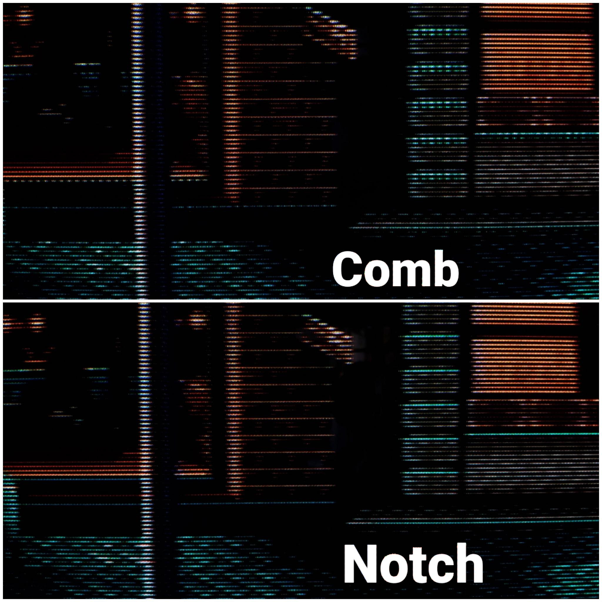
An example of a typical 2-line comb filter on a CRT (notice the hanging dots):</p>

<p><img src="/assets/img/CRT%20Comb%20CV2.jpg" alt="typical 2-line comb" /></p>

<p>The comb on my Toshiba MW24FM3 CRT (again, notice the hanging dots):</p>

<p><img src="/assets/img/IMG_20250920_142259.jpg" alt="toshiba comb" /></p>

<p>A mediocre comb on an LCD:</p>

<p><img src="/assets/img/LCD%20Comb%20CV2.jpg" alt="lcd comb" /></p>

<p>
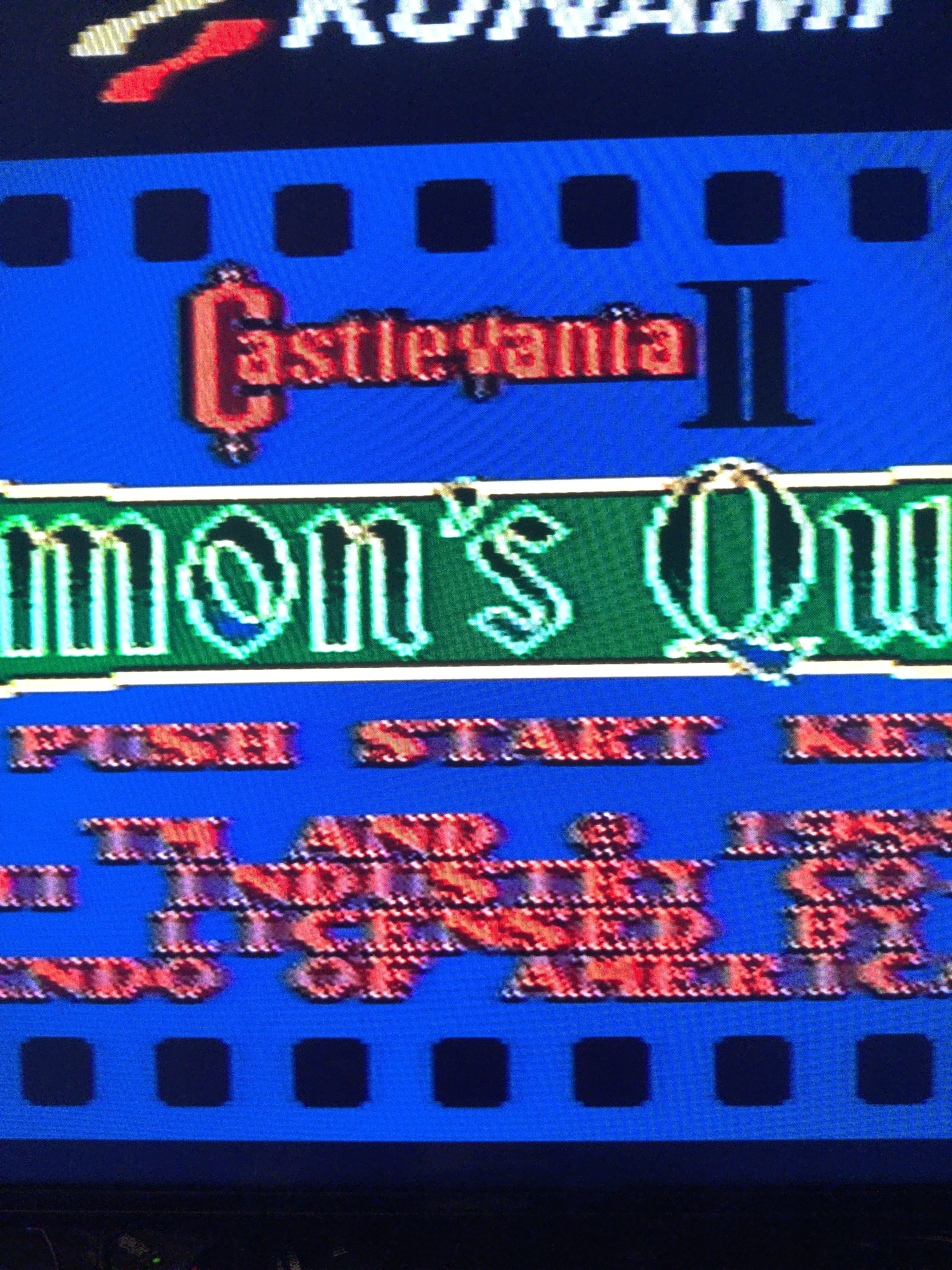
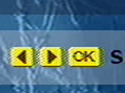
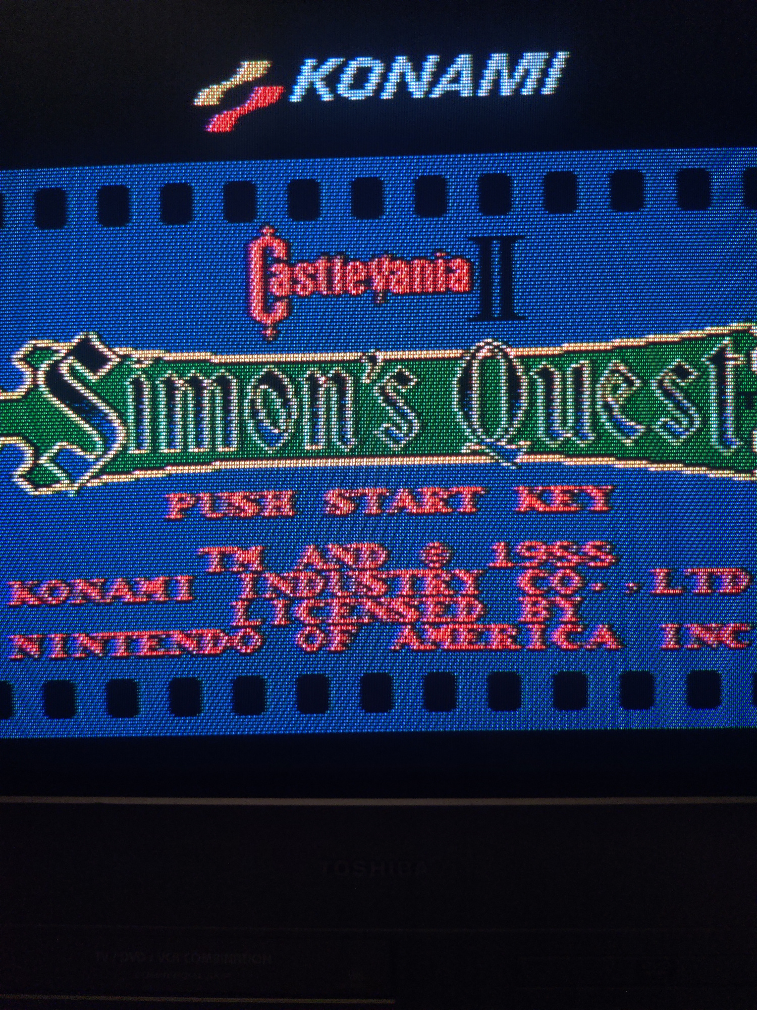
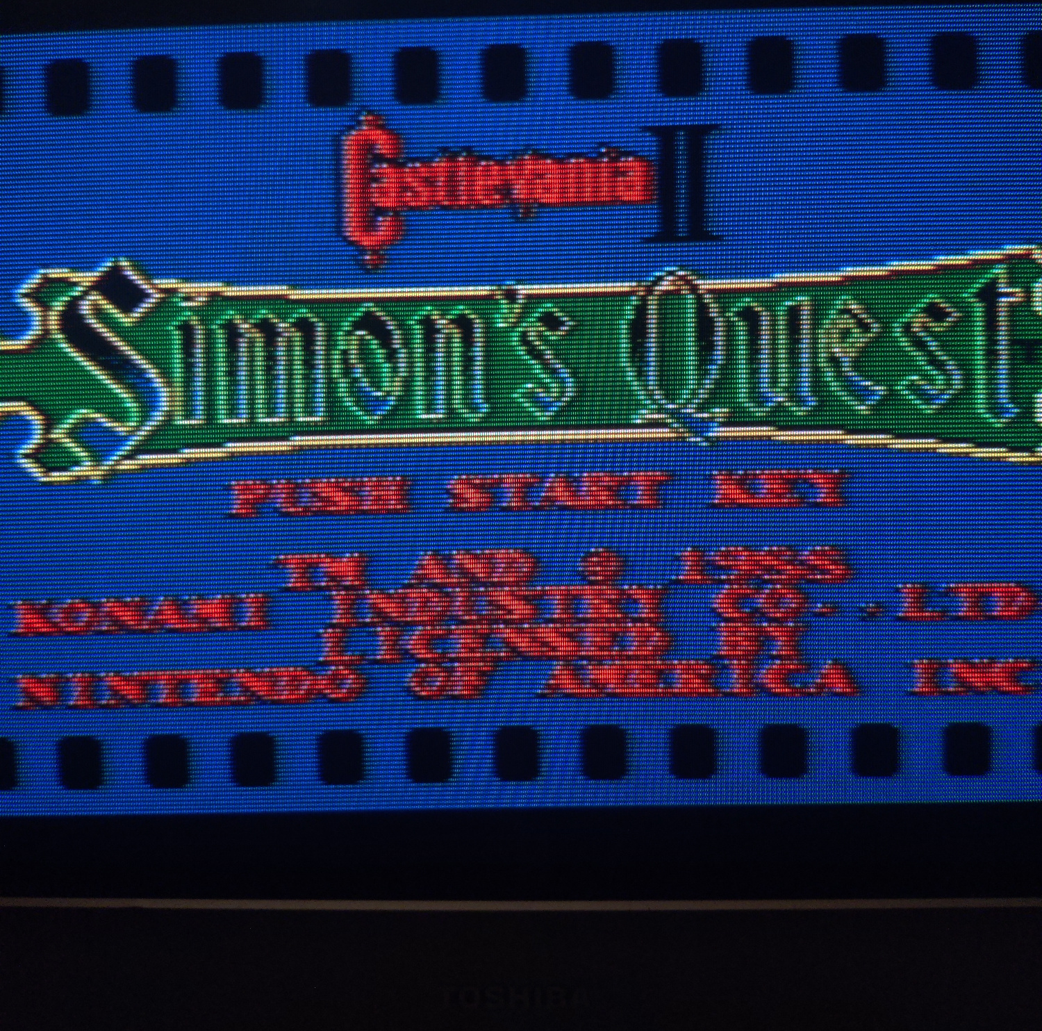
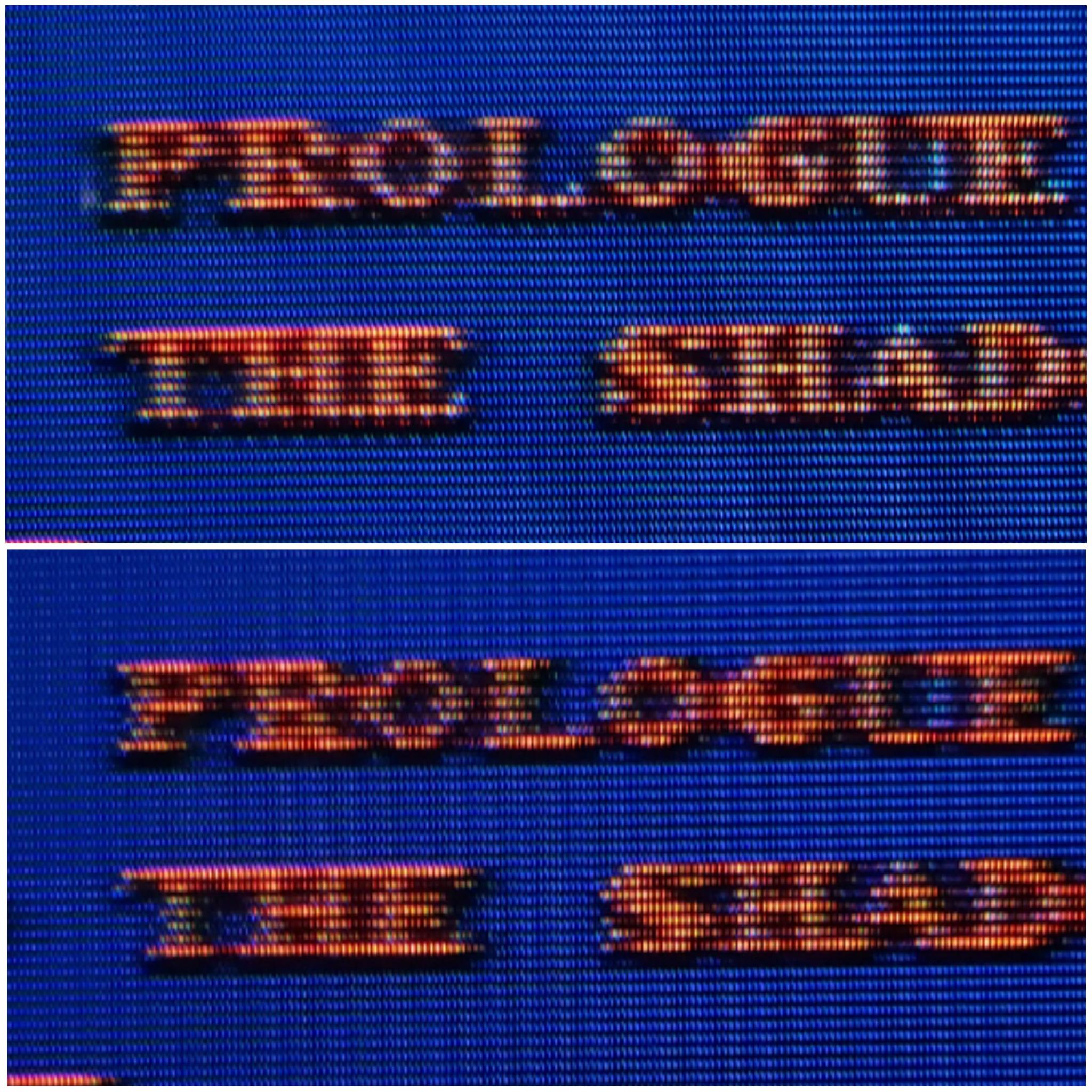
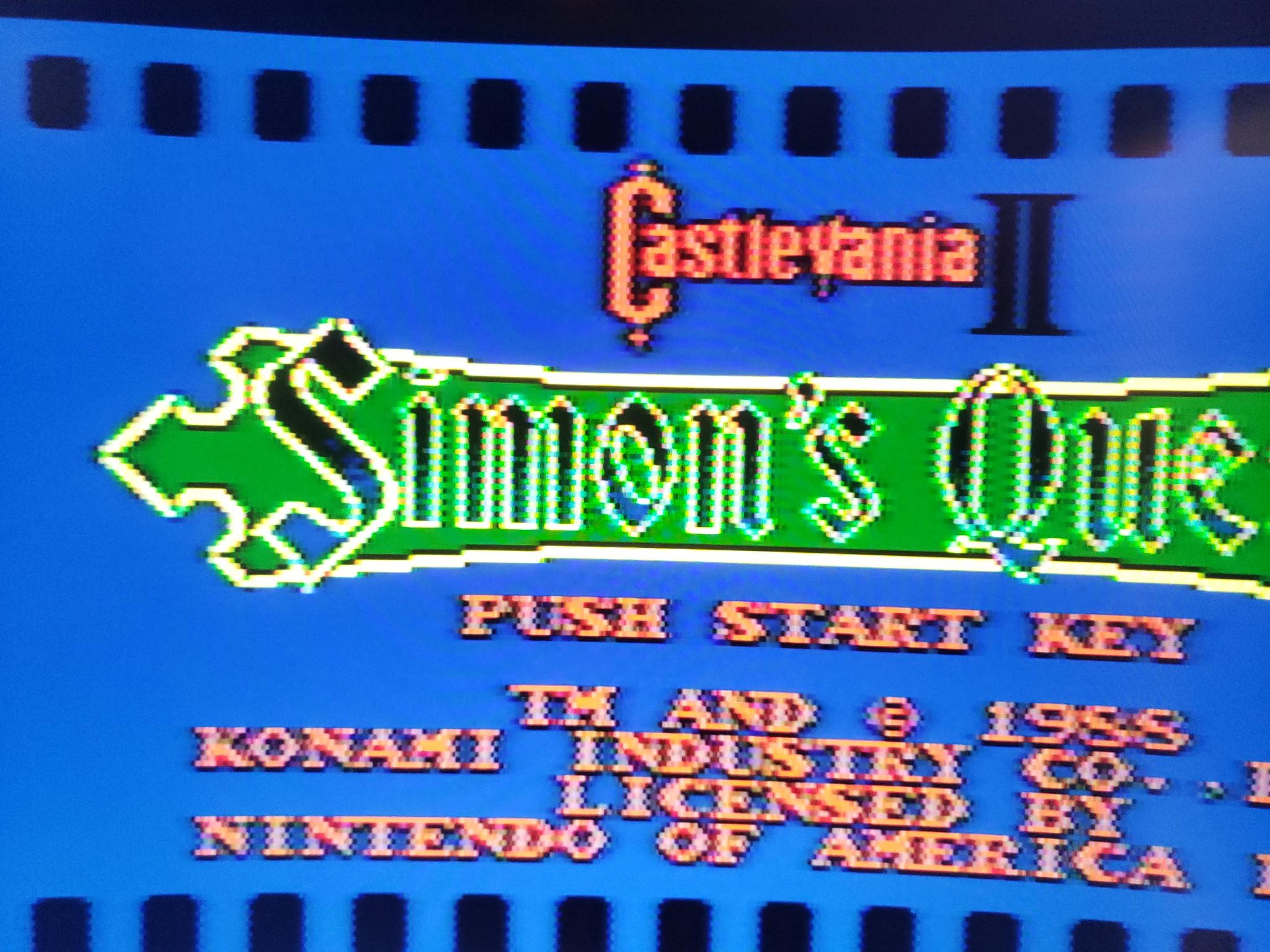
Comb (Top) vs. Notch (bottom) on Castlevania 2’s title screen text:</p>

<p><img src="/assets/img/signal-2025-08-21-10-14-19-560.jpg" alt="CV2 Comb Notch" /></p>

<p>
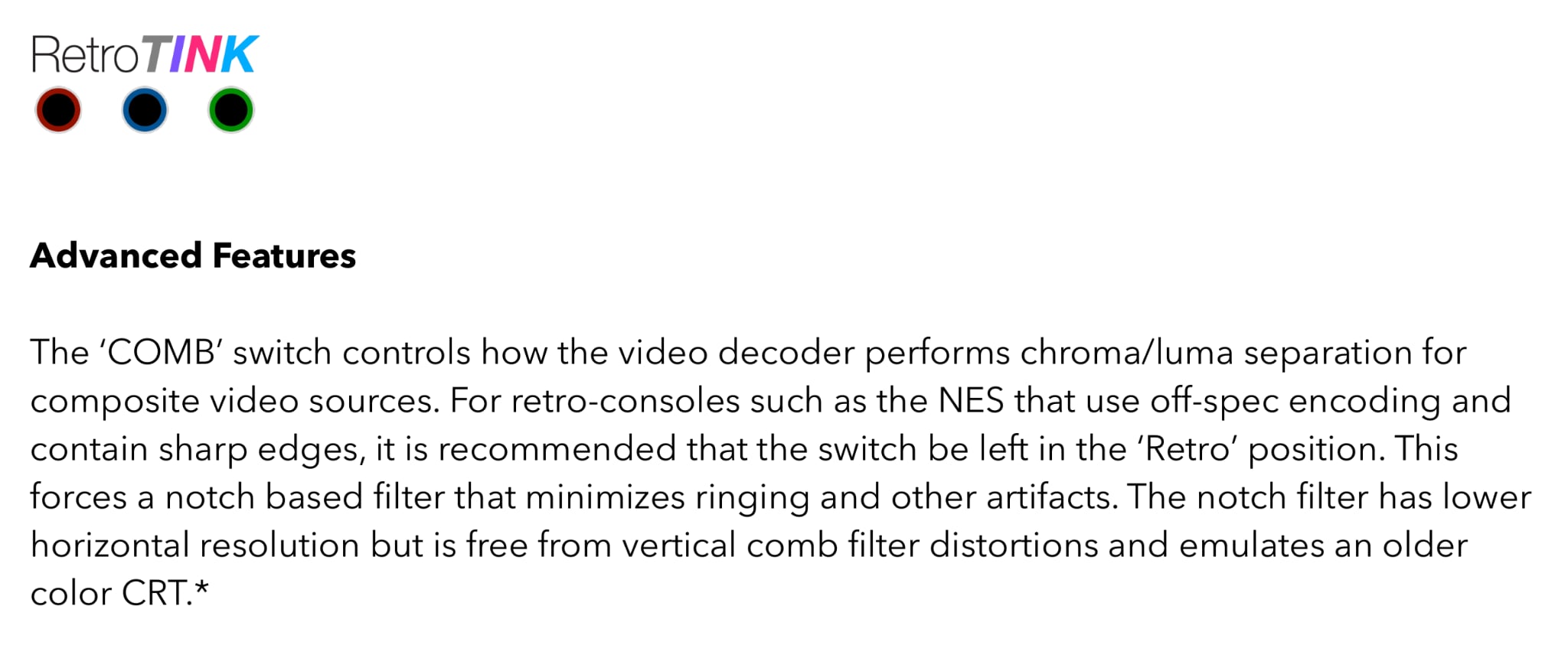
The notch filter on a RetroTink 5x on an LCD:</p>

<p><img src="/assets/img/tink%20notch.jpg" alt="RetroTink Notch" /></p>

<p>And that’s all I got!</p>

<p>I hope this article was helpful. Feel free to <a href="http://manadream.blog/about/">contact me</a> if you have any questions or suggestions for how to improve this article for others, and <a href="https://manadream.shop">go to my shop</a> to check out the manadream notch filter and other stuff I’ve made/modded.</p>

<h2 id="referencesfurther-reading">References/Further Reading:</h2>

<p><a href="https://en.wikipedia.org/wiki/NTSC">https://en.wikipedia.org/wiki/NTSC</a></p>

<p><a href="https://crtdatabase.com/articles/art-design">https://crtdatabase.com/articles/art-design</a></p>

<p><a href="https://en.wikipedia.org/wiki/Dot_crawl">https://en.wikipedia.org/wiki/Dot_crawl</a></p>

<p><a href="https://crtdatabase.com/articles/decoding-240p">https://crtdatabase.com/articles/decoding-240p</a></p>

<p><a href="https://www.extron.com/article/ntscdb1">https://www.extron.com/article/ntscdb1</a></p>

<p><a href="https://www.extron.com/article/ntscdb2">https://www.extron.com/article/ntscdb2</a></p>

<p><a href="https://www.extron.com/article/ntscdb3">https://www.extron.com/article/ntscdb3</a></p>

<p><a href="https://www.extron.com/article/ntscdb4">https://www.extron.com/article/ntscdb4</a></p>

<p><a href="https://nicole.express/2021/composite-conflict-completed.html">https://nicole.express/2021/composite-conflict-completed.html</a></p>]]></content><author><name></name></author><category term="Video" /><summary type="html"><![CDATA[When it comes to Composite video, there are two means of decoding the analog video stream, Notch and Comb filtering. This article will compare the two in the context of retro gaming by comparing several different external Notch and Comb filters.]]></summary></entry><entry><title type="html">Cheap S-Video and Composite USB Capture Card Comparison</title><link href="http://manadream.blog/2025/11/20/cheap-svideo-and-composite-usb-capture-card-comparison.html" rel="alternate" type="text/html" title="Cheap S-Video and Composite USB Capture Card Comparison" /><published>2025-11-20T00:00:00+00:00</published><updated>2025-11-20T00:00:00+00:00</updated><id>http://manadream.blog/2025/11/20/cheap-svideo-and-composite-usb-capture-card-comparison</id><content type="html" xml:base="http://manadream.blog/2025/11/20/cheap-svideo-and-composite-usb-capture-card-comparison.html"><![CDATA[<p>In this post I will go over a handful of S-Video and Composite capture devices that I tried when I was in the market for one,
and which one I found to be the highest quality as well as which is the best bang for your buck.</p>

<p>My goal was to capture S-Video from my various retro consoles, so that’s the metric this will be based on. 
I tried a total of 5 different USB capture devices, with a price range of $9 to $60. All of these have S-Video and Composite inputs.</p>

<p>All test pictures are from the 240p Test Suite running on a stock, recapped Genesis Model 1. Since it is not modded, there are some “jailbars”, a kind of video interference, in the source video.
I decided to not use a modded console to as to see how well the various capture cards handle imperfect video. I think it is a more faithful comparison.</p>

<h2 id="highest-quality-i-o-data-gv-usb2">Highest Quality: I-O DATA GV-USB2</h2>

<p><img src="/assets/img/I-O_DATA_GV-USB2_1-scaled-1290573213.jpg" alt="GV-USB2" /></p>

<p>Price: $60-$120</p>

<p>This is <a href="https://www.ebay.com/itm/405964367768">the listing</a> I purchased mine from. It was cheaper than buying from a US seller, so be aware that the price will be higher
from a US seller.</p>

<p>This one was recommended to me by a fellow CRT enthusiast and community member, kitty666cats/Mike Lindquist, and it turned out to be the highest quality picture of the ones I tested.</p>

<p><img src="/assets/img/GV-USB2%201.png" alt="Color Bars" />
<img src="/assets/img/GV-USB2%203.png" alt="240p Girl" />
<img src="/assets/img/GV-USB2%202.png" alt="240p Sonic" /></p>

<p>I used these specific settings in OBS as they were the best settings IMO.</p>

<p><img src="/assets/img/GV-USB2%20Settings.png" alt="Settings" /></p>

<p>While I say this is the best quality capture card, I did find the colors to be a little less saturated than I would like, and the input latency is higher than I would like.
I also had to make these adjustments in OBS for it to look right.
But for the purpose of capturing quality footage, this is the one I will be using.</p>

<h2 id="best-bang-for-your-buck-hdsunwstd-usb-20-avrca-composite-and-s-video-capture-card">Best Bang For Your Buck: HDSUNWSTD USB 2.0 AV/RCA Composite and S-Video Capture Card</h2>

<p><img src="/assets/img/HDSUNWSTD.jpg" alt="HDSUNWSTD" /></p>

<p>Price: ~$11</p>

<p>I got mine <a href="https://www.amazon.com/dp/B07P2V969C">from Amazon</a>, but there are various places you can get this one, just look for this particular case shape and design
as the name will be something different depending where you get it.</p>

<p><img src="/assets/img/hdsunwstd%201.png" alt="Color Bars" />
<img src="/assets/img/hdsunwstd%202.png" alt="240p Girl" />
<img src="/assets/img/hdsunwstd%203.png" alt="240p Sonic" /></p>

<p>The reason I say this is the best bang for your buck is that out of all the one I tested, this one had the 2nd highest quality capture,
decent input latency, and is only a few bucks more than the cheapest ones I tested. I personally find the color saturation to be
nicer than the GV-USB2, but it does come at the cost of more “jailbars” than the GV-USB2.</p>

<h2 id="others-i-tested">Others I Tested</h2>

<p>I’ll show the other ones I tested, in order of highest to lowest quality, so you can see how much variance there is with these cheap capture devices. I do not recommend these unless you for some reason like the way they look.</p>

<h3 id="1-tihokile-usb-vhs-to-digital-converter-for-rca-to-usb-convert">1. Tihokile USB VHS to Digital Converter for RCA to USB-Convert</h3>

<p><img src="/assets/img/TIHOKILE.jpg" alt="Tihokile" /></p>

<p>Price: ~$13</p>

<p>I got this <a href="https://www.amazon.com/dp/B0DBQ1G6C1">from Amazon</a>, and it’s not too bad. I’d say it’s the best of the worst (of the ones I tested). It definitely has noticeable jailbars.</p>

<p><img src="/assets/img/tihokile%201.png" alt="Color Bars" />
<img src="/assets/img/tihokile%202.png" alt="240p Girl" />
<img src="/assets/img/tihokile%203.png" alt="240p Sonic" /></p>

<p>I did have some issues with it needing to be plugged into the back USB ports of my computer, it kept resetting when plugged into the front ports, but that’s probably just my computer.</p>

<h3 id="2-nsendato-usb-20-type-c-av-s-video-capture-card-adapter">2. Nsendato USB 2.0 Type C AV S Video Capture Card Adapter</h3>

<p><img src="/assets/img/USB%202.0%20Type%20C%20AV%20S%20Video%20Capture%20Card.png" alt="Nsendato" /></p>

<p>Price: ~$7</p>

<p>This one comes <a href="">from AliExpress</a>. It’s pretty close to the Tihokile, with just slightly more jailbars being visible.</p>

<p><img src="/assets/img/USB%202.0%20Type%20C%20AV%20S%20Video%20Capture%20Card%20Adapter%20RCA%20AV%20Video%20Composite%20to%20USB%20Type%20C%20Converter%20Support%20NTSC%20PAL%20For%20Camera%20OBS%20PC.png" alt="Color Bars" />
<img src="/assets/img/USB%202.0%20Type%20C%20AV%20S%20Video%20Capture%20Card%20Adapter%20RCA%20AV%20Video%20Composite%20to%20USB%20Type%20C%20Converter%20Support%20NTSC%20PAL%20For%20Camera%20OBS%20PC%202.png" alt="240p Girl" />
<img src="/assets/img/USB%202.0%20Type%20C%20AV%20S%20Video%20Capture%20Card%20Adapter%20RCA%20AV%20Video%20Composite%20to%20USB%20Type%20C%20Converter%20Support%20NTSC%20PAL%20For%20Camera%20OBS%20PC%203.png" alt="240p Sonic" /></p>

<h3 id="3-tcnewcl-usb-audio-video-converter">3. TCNEWCL USB Audio Video Converter</h3>

<p><img src="/assets/img/USB%20Audio%20Video%20Converter.jpg" alt="TCNEWCL" /></p>

<p>Price: ~$10</p>

<p>This one is truly awful and I do not recommend it at all. I only captured the color bars and then promptly started the return process.</p>

<p><img src="/assets/img/USB%20Audio%20Video%20Converter,%20VHS%20to%20Digital%20Converter,%20Video%20Capture%20Card%20Digitize%20from%20Analog%20Video%20VCR%20VHS%20DVD,%20for%20Windows%207%208%2010.png" alt="Color Bars" /></p>

<p>Anb that’s all the ones I tested! I hope you find this helpful, and if you’re looking for a very high quality Composite to S-Video converter,
made specifically for retro gaming, <a href="https://manadream.shop/product/notch-filter-composite-to-s-video-converter">check out the one I have made</a>. I’m really proud of how well it came out.</p>]]></content><author><name></name></author><category term="Video" /><summary type="html"><![CDATA[In this post I will go over a handful of S-Video and Composite capture devices that I tried when I was in the market for one, and which one I found to be the highest quality as well as which is the best bang for your buck.]]></summary></entry><entry><title type="html">240p Test Suite on a Raspberry Pi for CRT Testing, Calibration and Repair</title><link href="http://manadream.blog/2025/11/09/240p-test-suite-on-a-raspberry-pi-for-crt-testing-calibration-repair.html" rel="alternate" type="text/html" title="240p Test Suite on a Raspberry Pi for CRT Testing, Calibration and Repair" /><published>2025-11-09T00:00:00+00:00</published><updated>2025-11-09T00:00:00+00:00</updated><id>http://manadream.blog/2025/11/09/240p-test-suite-on-a-raspberry-pi-for-crt-testing-calibration-repair</id><content type="html" xml:base="http://manadream.blog/2025/11/09/240p-test-suite-on-a-raspberry-pi-for-crt-testing-calibration-repair.html"><![CDATA[<p>I wanted a single, portable device for all my CRT repair needs, so I used a spare raspberry pi I had to run the 240p Test Suite.
I was unsatisfied with all the guides I found on getting composite output from a raspberry pi, they were all missing something or just no longer worked with the latest emulation distros.
I wanted something that accurately outputs 240p content, boots up as fast as possible, and has a simple, flexible UI. After some digging, I decided to use Lakka as the distro, with some key modifications for this use case.</p>

<p>Lakka is a Linux emulation distribution that directly uses RetroArch as its means of running games as well as for UI. There is no fancy EmulationStation-like interface to scroll around in and it has as little bloat as possible.
In addition to those benefits, using RetroArch as the means of rendering video allows us to customize the specifics of that output for each core that we want to use. This was the key to getting this to work how I wanted.</p>

<p>This guide will go over how to set this up on a Rapspberry Pi Zero, but it will work with most other Pis as well, with the difference being where to solder the composite video wires. I have notes about other Pis where needed.</p>

<p>There are, however, some Pis that have been confirmed not to work correctly with certain version of Lakka:</p>
<ul>
  <li>Original Pi 1 with RCA jack does not work at all (hangs at boot logo screen)</li>
  <li>Pi 3 with 64-bit/aarch64 image does not work (MUST use 32-bit/arm). Also note that one the Pi 3s that I have tried there is a weird black graphical glitch in the top right corner.</li>
  <li>Pi Zero 2W with Pi Zero 2 images does not work (MUST use 32-bit/arm Pi 3 image with <code class="language-plaintext highlighter-rouge">dtoverlay=vc4-kms-v3d,cma-384,composite=1</code> change to <code class="language-plaintext highlighter-rouge">dtoverlay=vc4-kms-v3d,composite=1</code> in <code class="language-plaintext highlighter-rouge">distroconfig-composite.txt</code>)</li>
</ul>

<h2 id="step-1-getting-composite-output-from-your-pi">Step 1: Getting Composite Output From Your Pi</h2>

<p>All Raspberry Pis can output composite video, but where the signal is output is different depending on the model.</p>

<p>If you get a black screen, or a weird thick, jagged white line and/or shifting video when you boot up your Pi using composite video, you soldered the wires incorrectly.</p>

<h3 id="pi-zero">Pi Zero</h3>

<p>For a Raspberry Pi Zero 1, the output is made available via 2 through-holes on the Pi’s PCB. They are labelled by a box around them with the text <code class="language-plaintext highlighter-rouge">TV</code> screen printed next to it.</p>

<p>Simply get a spare RCA or BNC cable that you can cut and use for this and solder the center/hot/signal wire to the left and the shield/ground wire to the right when looking at the board with the SD card on the left side. See the photo below.</p>

<p><img src="/assets/img/IMG_20251109_102049.jpg" alt="TV Out" /></p>

<p>Some Pi Zero 1s have the <code class="language-plaintext highlighter-rouge">TV</code> label on the left side of the box and some have it on the right, but where the wires go is not different. The video signal comes from the left side and the ground on the right.</p>

<h3 id="pi-zero-2">Pi Zero 2</h3>

<p>Solder an RCA cable to the TV and GND pads on the bottom of the PCB.</p>

<p>It’s important to solder to the correct pads. The video signal is from the pad to the LEFT of <code class="language-plaintext highlighter-rouge">TV</code> and ground is to the right of it. See the following image:</p>

<p><img src="/assets/img/IMG_20251125_013254.jpg" alt="TV Out" /></p>

<h3 id="pi-1-ab-through-pi-4-b">Pi 1 A+/B+ through Pi 4 B</h3>

<p>In the case of Pi 1 B+/A+ through 4 B, the 1/8” headphone jack is actually a TRRS AV out jack.</p>

<p>The cable you are using must have the correct polarity, check with a multimeter that the TRRS output is</p>

<table>
  <tbody>
    <tr>
      <td>Left Audio</td>
      <td>Right Audio</td>
      <td>Ground</td>
      <td>Video</td>
    </tr>
  </tbody>
</table>

<p>If it is not, the cable will not work correctly. Most TRRS cables that have RCA connectors on them are not correct and need to be rewired.</p>

<p>You can also purchase the correct cable <a href="https://www.adafruit.com/product/2881">from adafruit</a>.</p>

<h3 id="pi-5">Pi 5</h3>
<p>The Pi 5 has 2 through-holes on the PCB in a box labelled <code class="language-plaintext highlighter-rouge">VID</code> in between the <code class="language-plaintext highlighter-rouge">HMDI1</code> and <code class="language-plaintext highlighter-rouge">CAM/DISP 1</code> ports. Ground is the through-hole closest to the edge, and the video signal is the square pad.</p>

<h2 id="step-2-flash-lakka-and-configure-composite-video">Step 2: Flash Lakka and Configure Composite Video</h2>

<p>Each kind of Pi only works with this guide using a specific Lakka image.</p>

<p>Download the following Lakka image for your Pi <a href="https://www.lakka.tv/get/linux/rpi/">from their website</a>:</p>

<ul>
  <li>Pi Zero 1: “for Raspberry Pi Zero / Zero W (arm)”</li>
  <li>Pi Zero 2: “for Raspberry Pi 3 (arm)” <em>The images labelled for Pi zero 2 DO NOT WORK properly</em></li>
  <li>Pi 1 B+/A+: “for Raspberry Pi (arm)”</li>
  <li>Pi 2: “for Raspberry Pi 2 (arm)”</li>
  <li>Pi 3: “for Raspberry Pi 3 (arm)” <em>the file downloads as Lakka-RPi2.arm-5.0, this is fine</em></li>
  <li>Pi 4: “for Raspberry Pi 4 (aarch64)” <em>note: I have not tested a pi 4</em></li>
  <li>Pi 5: “for Raspberry Pi 5 (aarch64)” <em>note: I have not tested a pi 5</em></li>
</ul>

<p>Flash the image onto an SD card using one of the following USB flashers (or something you already know how to use):</p>

<ul>
  <li>Popsicle USB Flasher</li>
  <li>Balena Etcher</li>
  <li>win32diskimager</li>
</ul>

<p>Once it is done flashing, you’ll need to edit the boot config files to output composite video.</p>

<p>Reinsert the SD card into you computer so you can access the files on the SD card and modify them.</p>

<p>You should see the SD card show up as <code class="language-plaintext highlighter-rouge">LAKKA</code> in your file manager.</p>

<ol>
  <li>Open the SD card partition labelled <code class="language-plaintext highlighter-rouge">LAKKA</code> in your file manager.</li>
  <li>Open the file <code class="language-plaintext highlighter-rouge">config.txt</code> in a text editor.</li>
  <li>Find the line that has <code class="language-plaintext highlighter-rouge">include distroconfig.txt</code> and comment it out by adding a <code class="language-plaintext highlighter-rouge">#</code> to the beginning of the line.</li>
  <li>Find the line that has <code class="language-plaintext highlighter-rouge">#include distroconfig-composite.txt</code> and uncomment it by removing the <code class="language-plaintext highlighter-rouge">#</code> at the beginning of the line.</li>
  <li>Save these changes. Those two lines should now look like this:
    <div class="language-plaintext highlighter-rouge"><div class="highlight"><pre class="highlight"><code>#include distroconfig.txt
include distroconfig-composite.txt
</code></pre></div>    </div>
  </li>
  <li>Next, open the file <code class="language-plaintext highlighter-rouge">cmdline.txt</code> in a text editor.</li>
  <li>Add <code class="language-plaintext highlighter-rouge">video=Composite-1:720x480@60ie</code> to the end of the one line in the file and save it. It should look something like this (the UUIDs and other values will likely be different and there may be more than just these parameters in the file):
    <div class="language-plaintext highlighter-rouge"><div class="highlight"><pre class="highlight"><code>boot=UUID=1704-1837 disk=UUID=b6a5e937-7d11-4142-87f9-3c4a5a54cfa6 quiet console=tty0 video=Composite-1:720x480@60ie
</code></pre></div>    </div>
  </li>
  <li><strong>Raspberry Pi Zero 2 only:</strong> open <code class="language-plaintext highlighter-rouge">distroconfig-composite.txt</code> and change <code class="language-plaintext highlighter-rouge">dtoverlay=vc4-kms-v3d,cma-384,composite=1</code> to <code class="language-plaintext highlighter-rouge">dtoverlay=vc4-kms-v3d,composite=1</code> by removing <code class="language-plaintext highlighter-rouge">cma-384,</code> from that line.</li>
</ol>

<p>Save those file changes if you haven’t already, and insert the SD card into your pi and plug it into a Composite video monitor or CRT, then power it on.</p>

<p>Let it run and do its thing to finish setting up. Once it’s done and is booted to the Lakka menu, turn off the Pi and take the SD card out.</p>

<p><img src="/assets/img/IMG_20251109_125337.jpg" alt="Lakka Menu" /></p>

<h2 id="step-3-configuring-lakka-for-240p-output">Step 3: Configuring Lakka for 240p Output</h2>

<p>I created these configs to be as close as possible to the output of an actual SNES, NES and Genesis. I loaded the same 240p suite on the Pi and my consoles and went back and forth and adjusted the Pi’s core configs until the pictures were the same size and positioning as my consoles. You can adjust these to your liking, but they should be accurate and thus good for calibration and repair. I also set the Lakka UI layout and scale such that it is usable in 240p with these configs.</p>

<p>Reinsert the SD card into you computer so you can access the files on the SD card and modify them.</p>

<p>NOTE: On Mac or Windows you will have to do this section via SSH if you cannot mount ext3/ext4 filesystems. See <a href="https://www.lakka.tv/doc/Accessing-Lakka-filesystem/">this guide on Lakka’s site</a> if you are not using Linux to learn how you can edit files on the ext3/ext4 partition. If you are using Linux, the following guide is exactly what you need to do.</p>

<p>Once you understand and are able to edit text files on the SD card, do the following:</p>

<ol>
  <li>Open the SD card partition labelled <code class="language-plaintext highlighter-rouge">LAKKA_DISK</code> in your file manager (or access the pi over SSH and you’ll be in this location by default).</li>
  <li>Navigate to the folder <code class="language-plaintext highlighter-rouge">.config/retroarch/config/</code> (you may need to access it as root/admin). NOTE: if you are accessing the Pi via SSH, the full path is <code class="language-plaintext highlighter-rouge">/storage/.config/retroarch/config/</code></li>
  <li>Create the folder <code class="language-plaintext highlighter-rouge">QuickNES</code> in <code class="language-plaintext highlighter-rouge">.config/retroarch/config/</code> and place the following text in a file called <code class="language-plaintext highlighter-rouge">QuickNES.cfg</code> in the <code class="language-plaintext highlighter-rouge">QuickNES</code> folder you just created (this is the NES core that will be used).
    <div class="language-plaintext highlighter-rouge"><div class="highlight"><pre class="highlight"><code>aspect_ratio_index = "23"
custom_viewport_height = "224"
custom_viewport_width = "642"
custom_viewport_x = "45"
custom_viewport_y = "6"
video_fullscreen_x = "720"
video_fullscreen_y = "240"
xmb_layout = "1"
menu_scale_factor = "0.75"
</code></pre></div>    </div>
  </li>
  <li>Create the folder <code class="language-plaintext highlighter-rouge">PicoDrive</code> in <code class="language-plaintext highlighter-rouge">.config/retroarch/config/</code> and place the following text in a file called <code class="language-plaintext highlighter-rouge">PicoDrive.cfg</code> in the <code class="language-plaintext highlighter-rouge">PicoDrive</code> folder you just created (this is the Genesis/Mega Drive core that will be used). Note that some games do not produce audio properly on some versions of PicoDrive (I personally noticed Sonic and Knuckles and Sonic 2 have this problem), but I chose it because it runs the games the fastest.
    <div class="language-plaintext highlighter-rouge"><div class="highlight"><pre class="highlight"><code>aspect_ratio_index = "23"
custom_viewport_height = "224"
custom_viewport_width = "642"
custom_viewport_x = "37"
custom_viewport_y = "8"
video_fullscreen_x = "720"
video_fullscreen_y = "240"
xmb_layout = "1"
menu_scale_factor = "0.75"
</code></pre></div>    </div>
  </li>
  <li>Create the folder <code class="language-plaintext highlighter-rouge">Snes9x 2002</code> in <code class="language-plaintext highlighter-rouge">.config/retroarch/config/</code> and place the following text in a file called <code class="language-plaintext highlighter-rouge">Snes9x 2002.cfg</code> in the <code class="language-plaintext highlighter-rouge">Snes9x 2002</code> folder you just created (this is the SNES core that will be used). I chose 2002 because it performs the best of the Snes9x cores.
    <div class="language-plaintext highlighter-rouge"><div class="highlight"><pre class="highlight"><code>aspect_ratio_index = "23"
custom_viewport_height = "224"
custom_viewport_width = "646"
custom_viewport_x = "37"
custom_viewport_y = "7"
video_fullscreen_x = "720"
video_fullscreen_y = "240"
xmb_layout = "1"
menu_scale_factor = "0.75"
</code></pre></div>    </div>
  </li>
</ol>

<p>Now when you load a rom using one of these three cores, they will correctly display in 240p.</p>

<h2 id="step-4-copy-240p-test-suites-to-the-pi">Step 4: Copy 240p Test Suites to the Pi</h2>

<p>With your SD card still inserted, download the SNES and Genesis 240p Test Suites <a href="https://artemiourbina.itch.io/240p-test-suite">from here</a>, rename them to <code class="language-plaintext highlighter-rouge">240p-SNES.sfc</code> and <code class="language-plaintext highlighter-rouge">240p-Genesis.bin</code> (or whatever you want) and copy them to the <code class="language-plaintext highlighter-rouge">roms</code> folder on <code class="language-plaintext highlighter-rouge">LAKKA_DISK</code>.</p>

<p>Then download the NES 240p Test Suite <a href="https://github.com/pinobatch/240p-test-mini/releases">from here</a> (it’s the file called 240pee.nes), rename it to <code class="language-plaintext highlighter-rouge">240p-NES.nes</code> and copy it to the <code class="language-plaintext highlighter-rouge">roms</code> folder.</p>

<p>Finally, add whatever other test roms you want to the <code class="language-plaintext highlighter-rouge">roms</code> folder.</p>

<h2 id="step-5-connect-a-controller-and-boot-it-up">Step 5: Connect a Controller and Boot it up</h2>

<p>Get a USB controller (and a micro USB to USB A adapter if you’re using a Pi Zero). I used a simple SNES style controller.</p>

<p><img src="/assets/img/IMG_20251109_104258.jpg" alt="Controller" /></p>

<p>Connect the controller to the pi, connect the Composite video output to a Composite display or CRT, and then connect power.</p>

<p>You should see it boot up and display the main menu in 480i mode.</p>

<p><img src="/assets/img/IMG_20251109_125337.jpg" alt="Lakka Menu" /></p>

<p>You’re going to want to set the hotkey controller combo to get back to the Lakka menu from running a game.</p>

<ol>
  <li>With your controller, go right to the gears icon and down to <code class="language-plaintext highlighter-rouge">Input</code> and select it.</li>
</ol>

<p><img src="/assets/img/IMG_20251109_125356.jpg" alt="Input Menu" /></p>

<ol>
  <li>Go down to <code class="language-plaintext highlighter-rouge">Hotkeys</code> and select it, then go down to <code class="language-plaintext highlighter-rouge">Menu Toggle (Controller Combo)</code> and select it.</li>
  <li>Choose a combo that makes sense for you and your controller. I selected <code class="language-plaintext highlighter-rouge">Hold Start (2 seconds)</code>, but whatever you want is fine so long as your controller actually has the button combo chosen.</li>
</ol>

<p><img src="/assets/img/IMG_20251109_125423.jpg" alt="Hotkey" /></p>

<p>Then back out all the way back to the top menu. You can now test out your 240p setup to make sure it’s working right.</p>

<ol>
  <li>Go down to <code class="language-plaintext highlighter-rouge">Load Content</code> and select it.</li>
  <li>Choose <code class="language-plaintext highlighter-rouge">Start Directory</code> and you should see the roms you put in the <code class="language-plaintext highlighter-rouge">roms</code> folder</li>
  <li>Go down to <code class="language-plaintext highlighter-rouge">240p-SNES.sfc</code> and select it, then select <code class="language-plaintext highlighter-rouge">Nintendo - SNES / SFC (Snes9x 2002)</code> as the core. This is very important as the settings override was set for this core only.</li>
  <li>You should see the 240p Test Suite boot up and be rendering in 240p. If the image is flickering at all (which means it’s in 480i) or if the picture is really narrow and in the center, then you need to go back and make sure you set the configs correctly.</li>
</ol>

<p><img src="/assets/img/IMG_20251109_125454.jpg" alt="240p Test Suite on SNES" /></p>

<ol>
  <li>Press the hotkey controller combo you set and you should see the Lakka menu appear.</li>
  <li>Go down and select <code class="language-plaintext highlighter-rouge">Close Content</code> and you should be brought back to the main Lakka menu.</li>
</ol>

<p>If this all went well and looks correct, do the same for the NES 240p suite on the <code class="language-plaintext highlighter-rouge">Nintendo - NES / Famicom (QuickNES)</code> core and Genesis 240p on the <code class="language-plaintext highlighter-rouge">Sega - MS/GG/MD/CD/32X (PicoDrive)</code> core.</p>

<p>If something looks off with any of them or it’s not rendering in 240p, go back and check that the configuration was done correctly.</p>

<p>To make it easier to access the roms with the correct core, from the menu you access with the controller combo hotkey you can select <code class="language-plaintext highlighter-rouge">Add to Favorites</code> and then you will be able to launch the rom from the Lakka main menu’s Favorites section which looks like a Star icon.</p>

<p>And that’s it! You now have a portable CRT testing device :)</p>

<p>If you want my exact setup, you can also <a href="/assets/txt/retroarch.cfg">download my retroarch.cfg file</a> and replace yours with it. It’s mostly getting rid of menu items that are not necessary for this.</p>

<h2 id="bonus-step-get-audio-from-your-pi">Bonus Step: Get Audio from your Pi</h2>

<p>To get analog audio from a Pi Zero or a Pi 5 is a little more involved, and I recommend <a href="https://learn.adafruit.com/introducing-the-raspberry-pi-zero/audio-outputs">this guide</a> for that. Alternatively, you can get a USB Audio device that has a headphone output and then get a headphone (1/8” or 3.5mm) to RCA cable. You’d then need to follow the steps below, but for <code class="language-plaintext highlighter-rouge">audio_device</code> you’d need to determine what your USB audio device ID is by SSHing into the pi and running <code class="language-plaintext highlighter-rouge">aplay -L</code>, so that’s for advanced users. Yet another option is to get an HDMI Audio extractor to use the HDMI audio output, but at that point you might as well get a different Pi.</p>

<p>Here I will cover the few extra steps you need to get audio from your Pi 1 through 4 (this was done on a Pi 1).</p>

<ol>
  <li>Edit the <code class="language-plaintext highlighter-rouge">config.txt</code> file in the <code class="language-plaintext highlighter-rouge">LAKKA</code> partition of the SD card and uncomment these two lines by removing the <code class="language-plaintext highlighter-rouge">#</code> at the beginning (should look like this after):
    <div class="language-plaintext highlighter-rouge"><div class="highlight"><pre class="highlight"><code>dtparam=audio=on
audio_pwm_mode=1
</code></pre></div>    </div>
  </li>
  <li>In <code class="language-plaintext highlighter-rouge">.config/retroarch/retroarch.cfg</code> set the <code class="language-plaintext highlighter-rouge">audio_device</code> line to this:
    <div class="language-plaintext highlighter-rouge"><div class="highlight"><pre class="highlight"><code>audio_device = "default:CARD=Headphones"
</code></pre></div>    </div>
  </li>
  <li>In the same config file, make sure <code class="language-plaintext highlighter-rouge">audio_enable</code> is true, like this:
    <div class="language-plaintext highlighter-rouge"><div class="highlight"><pre class="highlight"><code>audio_enable = "true"
</code></pre></div>    </div>
  </li>
</ol>

<p>Save those changes and you should now be able to get sound and video from your TRRS cable connected to the Pi.</p>

<p>REMINDER: Your TRRS cable needs to be correctly wired as Left(T), Right(R), Ground(R), Video(S). All TRRS cables with  RCA connectors that I have randomly acquired have not been wired this way, so either modify your cable if it is not correct or buy one that is specifically for a Pi.</p>

<hr />

<p>Files:</p>

<p><a href="/assets/txt/QuickNES.cfg">QuickNES.cfg</a></p>

<p><a href="/assets/txt/PicoDrive.cfg">PicoDrive.cfg</a></p>

<p><a href="/assets/txt/Snes9x%202002.cfg">Snes9x 2002.cfg</a></p>

<p><a href="/assets/txt/retroarch.cfg">retroarch.cfg</a></p>]]></content><author><name></name></author><category term="CRT" /><summary type="html"><![CDATA[I wanted a single, portable device for all my CRT repair needs, so I used a spare raspberry pi I had to run the 240p Test Suite. I was unsatisfied with all the guides I found on getting composite output from a raspberry pi, they were all missing something or just no longer worked with the latest emulation distros. I wanted something that accurately outputs 240p content, boots up as fast as possible, and has a simple, flexible UI. After some digging, I decided to use Lakka as the distro, with some key modifications for this use case.]]></summary></entry><entry><title type="html">Sony KV-32FS13 - RGB SCART Mod</title><link href="http://manadream.blog/2025/10/29/sony-kv-32fs13-rgb-mod.html" rel="alternate" type="text/html" title="Sony KV-32FS13 - RGB SCART Mod" /><published>2025-10-29T00:00:00+00:00</published><updated>2025-10-29T00:00:00+00:00</updated><id>http://manadream.blog/2025/10/29/sony-kv-32fs13-rgb-mod</id><content type="html" xml:base="http://manadream.blog/2025/10/29/sony-kv-32fs13-rgb-mod.html"><![CDATA[<p>This guide will cover how to RGB SCART mod the 32” Sony KV32-FS13. RGB Modding this CRT isn’t too difficult, the hardest part is making the RGB SCART hole for the port imo.</p>

<p><img src="/assets/img/IMG_20251027_010053.jpg" alt="set" /></p>

<p>I installed the RGB mod using Sunthar’s guide, which you can see <a href="https://sector.sunthar.com/guides/crt-rgb-mod/sony-kv-32fs13.html">here</a> for additional references.</p>

<h2 id="step-1-removereplace-components">Step 1: Remove/Replace components</h2>

<p>Open up your CRT and pull out the PCB on the left side of the TV (There are 3 in total, the center main board, the left board, and a small power board on the right). You may need to unplug some connectors and pull the other two boards out in order to pull this board out.</p>

<p>On the bottom of this board, locate R086, R087 and R088 and remove them.</p>

<p><img src="/assets/img/IMG_20251026_200401.jpg" alt="remove resistors" /></p>

<p>Then locate the three jumper wires shown in the image below and remove them. They are just above the resistors you removed and are labelled on the top as JW341, JW342 and JW343.</p>

<p><img src="/assets/img/IMG_20251026_201545.jpg" alt="remove jumpers" /></p>

<p>Insert three 1N4148 diodes where those jumpers were removed. Make sure the cathode (the black line on the diode) is on the left side when reading the jumper labels on the top of the board, or on the side closest to the connector CN303.</p>

<p><img src="/assets/img/IMG_20251026_202140.jpg" alt="insert diodes" /></p>

<h2 id="step-2-connect-wires-to-go-to-scart-port">Step 2: Connect Wires to go to SCART Port</h2>

<p>As you can see in the previous image, we will be injecting the RGB and Blanking signals at the cathode sides of the diodes you inserted for RGB, and into the jumper wire for Blanking.</p>

<p><strong>IMPORTANT NOTE</strong>: I highly recommend you use shielded cable for the RGB signals, otherwise you will most likely get a lot of noise in your RGB signals that will appear in the video on screen. It looks really bad, like there’s moving noise across the screen. You can get shielded 3-wire cable on the internet pretty easily.</p>

<p>Connect RGB and Blanking leads from your shielded wire to the board as shown below.</p>

<p><img src="/assets/img/IMG_20251029_162201.jpg" alt="connect RGB and Blanking" /></p>

<p>Then connect the ground of your shielded wire to the anode side of D301 as shown below (or any suitable ground point).</p>

<p><img src="/assets/img/IMG_20251029_162153.jpg" alt="ground" /></p>

<p>Next, connect wires to the back of the S-Video input jack on the main, center board as shown below. Sync connects to the Y input of the S-Video jack, the other wire is for ground (if using the shielded cable ground this is not necessary but I used it anyway for an extra ground connection).</p>

<p><img src="/assets/img/IMG_20251026_203529.jpg" alt="sync" /></p>

<p>Then connect wires to the underside of the main board S-Video AV jack for your Left and Right Audio.</p>

<p><img src="/assets/img/IMG_20251026_205233.jpg" alt="audio" /></p>

<p>That’s all the wires you’ll need to connect to your SCART port.</p>

<h2 id="step-3-prepare-your-scart-port">Step 3: Prepare your SCART Port</h2>

<p>If you purchased a SCART port from Sunthar, you can follow the instructions on <a href="https://sector.sunthar.com/guides/crt-rgb-mod/sony-kv-32fs13.html#step-3-build-your-mux-board">his guide</a> for this section.</p>

<p>CRT Database also has a <a href="https://crtdatabase.com/modding/wiring-and-installing-a-scart-connector">great guide</a> on creating a clean SCART connector setup, so check that out as well for more info.</p>

<p>If you want to make your own, I used <a href="https://www.aliexpress.us/item/3256807009901234.html">this</a> SCART female socket from AliExpress, which you can find elsewhere. The Ali listing calls it a <code class="language-plaintext highlighter-rouge">21 PINS CS Type Scart Female Socket Connector Jack Female PCB Mount 21 PIN SCART</code></p>

<p>I then used some prototyping board I had laying around and broke a piece large enough to connect what I needed to it. You can also do this without a board, you’ll just need to make sure to connect your components with enough support that they won’t break off during use/install/movement.</p>

<p>Use the following diagram <a href="https://sunthar.com/rgb-mux-calculator?data=eyJjciI6NTYwMCwiY2ciOjY4MCwidCI6NzUsImkiOjEwMDAsImJnIjoiIiwiYmkiOjEyMDAsImNzIjp0cnVlLCJ2cHAiOiIiLCJtb2RlIjoib3V0cHV0Vm9sdGFnZSIsImNiciI6MTAwMCwiY2JnIjozMzAwLCJjbiI6IkMzOTUsIEMzNTMsIEMzNTIiLCJjdiI6IjAuMDEiLCJvcCI6IjY0LDYzLDYyLDYxIiwianAiOiI0Myw0Miw0MSw0MCIsInJpIjoiUjAyNSxSMDI2LFIwMjcsUjAyOCIsImdpIjoiUjA4NixSMDg3LFIwODgsUjAwNCIsInJkIjp0cnVlLCJiZCI6dHJ1ZSwiaWQiOnRydWUsIm10IjpmYWxzZSwiZGkiOmZhbHNlLCJjaSI6ZmFsc2UsImJsIjpmYWxzZSwiY2wiOmZhbHNlLCJiZHAiOnRydWUsImJhbCI6ZmFsc2UsInJhbCI6dHJ1ZSwiYmluIjoiTE4wMDMiLCJ2IjowLjY5LCJvc2RfdiI6NSwibSI6IlNvbnkgS1YtMzJGUzEzIiwibyI6bnVsbCwiaiI6bnVsbCwiZGljIjp7ImM0IjowLjEsImM1IjowLjEsImM2IjowLjF9LCJyMTIiOjEwMDB9">made using Sunthar’s mux calculator</a> to create your RGB SCART MUX.</p>

<p><img src="/assets/img/RGB_MUX_Diagram_Sony_KV-32FS13.png" alt="RGB MUX" /></p>

<p>TLDR info is:</p>

<ul>
  <li>RGB inputs are 75 Ohm terminated then connect to your shielded RGB wires from earlier with 1K Ohm resistors.</li>
  <li>The Blanking input is connected to a 1N4148 diode, then a 1.0K-2.2K Ohm resistor to the blanking jumper from earlier (I used 1.2K Ohms but 1K works fine and Sunthar recommended 2.2K)</li>
  <li>Sync input is connected directly to the S-Video sync wire soldered earlier.</li>
  <li>Audio left and right are connected to the audio wires soldered earlier with 1K Ohm resistors inline.</li>
  <li>Ground is connected to ground through the Shielded RGB cable’s ground, or through another ground, or both.</li>
  <li>MAKE SURE to connect your shielded cable’s ground to the chassis and to the SCART port.</li>
</ul>

<p>You can see how I made my SCART board in the image below.</p>

<p><img src="/assets/img/IMG_20251029_162126.jpg" alt="SCART MUX" /></p>

<p>That’s all for the wiring, you should now test your work to ensure that it is all functioning properly.</p>

<h2 id="step-4-mounting-the-scart-port">Step 4: Mounting the SCART port</h2>

<p>I used a <a href="https://www.printables.com/model/1446440-scart-female-connector-plate">3D-printed SCART port panel</a> to cover up any not-so-perfect cutting I did for the port.</p>

<p>To do the actual cutting I drew an outline of the port using the 3D-printed part and then used a dremel to cut the outline out. I then needed to use a razor blade to trim the plastic more until it fit snug. Then I drilled holes to screw into the port with using some screws I found that were the right size to thread into the plastic of the SCART port. You can see the final results below.</p>

<p><img src="/assets/img/IMG_20251027_124305.jpg" alt="SCART Port" /></p>

<p>And that’s it for the mod! You’ll need to be on the Video 1 input and the picture will appear when you plug in a console and turn it on. If you go to other video inputs when the SCART connected console is on, you will see a scrolling image because it is not getting sync since sync is tied to input 1. If you want SCART to be a different input you can wire Sync to that input.</p>

<p><img src="/assets/img/IMG_20251027_010443.jpg" alt="example" />
<img src="/assets/img/IMG_20251027_010752.jpg" alt="example" />
<img src="/assets/img/IMG_20251029_162744.jpg" alt="example" />
<img src="/assets/img/IMG_20251029_162755.jpg" alt="example" /></p>

<p>This article is also hosted on <a href="https://electron.sunthar.com/manadream/article/sony-kv-32fs13-rgb-scart-mod">Sunthar.com</a></p>]]></content><author><name></name></author><category term="CRT" /><summary type="html"><![CDATA[This guide will cover how to RGB SCART mod the 32” Sony KV32-FS13. RGB Modding this CRT isn’t too difficult, the hardest part is making the RGB SCART hole for the port imo.]]></summary></entry><entry><title type="html">Power Supply Video Noise Solution</title><link href="http://manadream.blog/2025/08/31/power-supply-video-noise-solution.html" rel="alternate" type="text/html" title="Power Supply Video Noise Solution" /><published>2025-08-31T00:00:00+00:00</published><updated>2025-08-31T00:00:00+00:00</updated><id>http://manadream.blog/2025/08/31/power-supply-video-noise-solution</id><content type="html" xml:base="http://manadream.blog/2025/08/31/power-supply-video-noise-solution.html"><![CDATA[<p>I run all my consoles through a receiver to select which one to display on my CRT. One day I noticed that there was a lot of noise in the video from my Sega Genesis.</p>

<p><img src="/assets/img/IMG_20250831_194625.jpg" alt="Genesis noise" />
<img src="/assets/img/IMG_20250831_194731.jpg" alt="Genesis noise" /></p>

<p>As you can see, it’s most noticeable on dark colors or a black screen, and it would slowly roll from the bottom of the screen to the top. I didn’t see this same noise on my other consoles and so I looked into why that was. Turns out it was noise coming from the power supply. I tried 3 different ones and they all had some noise, the two larger ones from AliExpress were particularly bad.</p>

<p><img src="/assets/img/IMG_20250831_195122.jpg" alt="Bad power supplies" /></p>

<p>I then tried the power supply that I was using for my NES and SNES on the Genesis and the noise was gone!</p>

<p><img src="/assets/img/IMG_20250831_201622.jpg" alt="Genesis noise gone" />
<img src="/assets/img/IMG_20250831_195158.jpg" alt="Genesis noise gone" /></p>

<p>I looked into what the difference was by opening them all up.</p>

<p><img src="/assets/img/IMG_20250812_181818.jpg" alt="Transformer power supply" />
<img src="/assets/img/IMG_20250831_213242.jpg" alt="Switching power supply" /></p>

<p>The power supply I was using for my NES and SNES is one of those old heavy brick style power supplies that has nothing more than a transformer, a diode bridge, and a large capacitor. The others were all switching power supplies, a more efficient technology but clearly more noisy.</p>

<p>There are probably higher quality switching power supplies than the ones I have (one of them did produce much less noise than the others), but using the simpler, heavier one got rid of the noise. So if you encounter this type of noise in the video of your retro consoles, it might be the power supply.</p>]]></content><author><name></name></author><category term="Video" /><summary type="html"><![CDATA[I run all my consoles through a receiver to select which one to display on my CRT. One day I noticed that there was a lot of noise in the video from my Sega Genesis.]]></summary></entry></feed>